Classic R #27 Build - Final Assembly - Part 2
2 posters
Page 1 of 1
 Classic R #27 Build - Final Assembly - Part 2
Lots of progress to report over the last couple of weeks. I've been pushing to get the braking system finished and to get the engine to a point where I can turn it over on the starter.
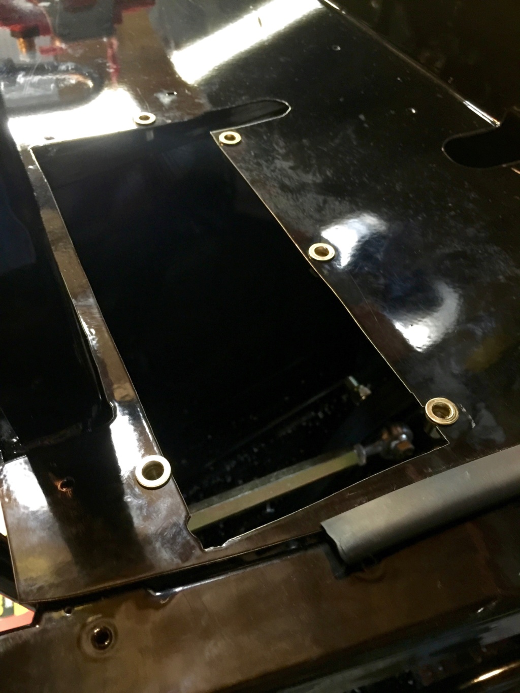
Before reinstalling the brake booster I had to put the tray that fits underneath it back in. I opted to secure it with rivnuts, shown here. These are M5s, the smallest size that my rivnut tool can handle.
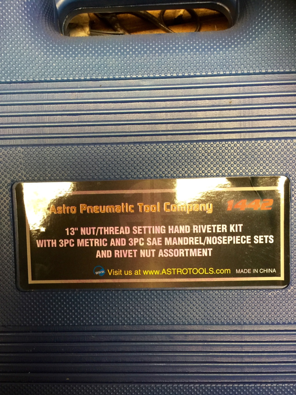
And here's the offending tool. I haven't been disappointed with Astro gear so far and I have a few odds and ends of theirs, including this rivnut installer and a weatherpack/metripack crimp tool kit.
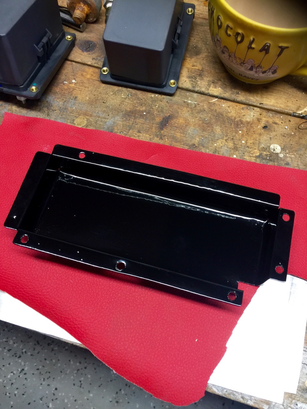
Powdercoated tray, ready to reinstall under the brake booster.
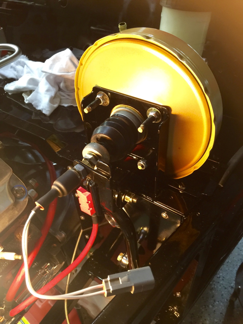
Here's the brake booster, cleaned up, derusted and repainted before installation. I used left over paint from an Eastwood CAD paint kit. That paint has held up very well in my MG, so I see no reason not to use it here.
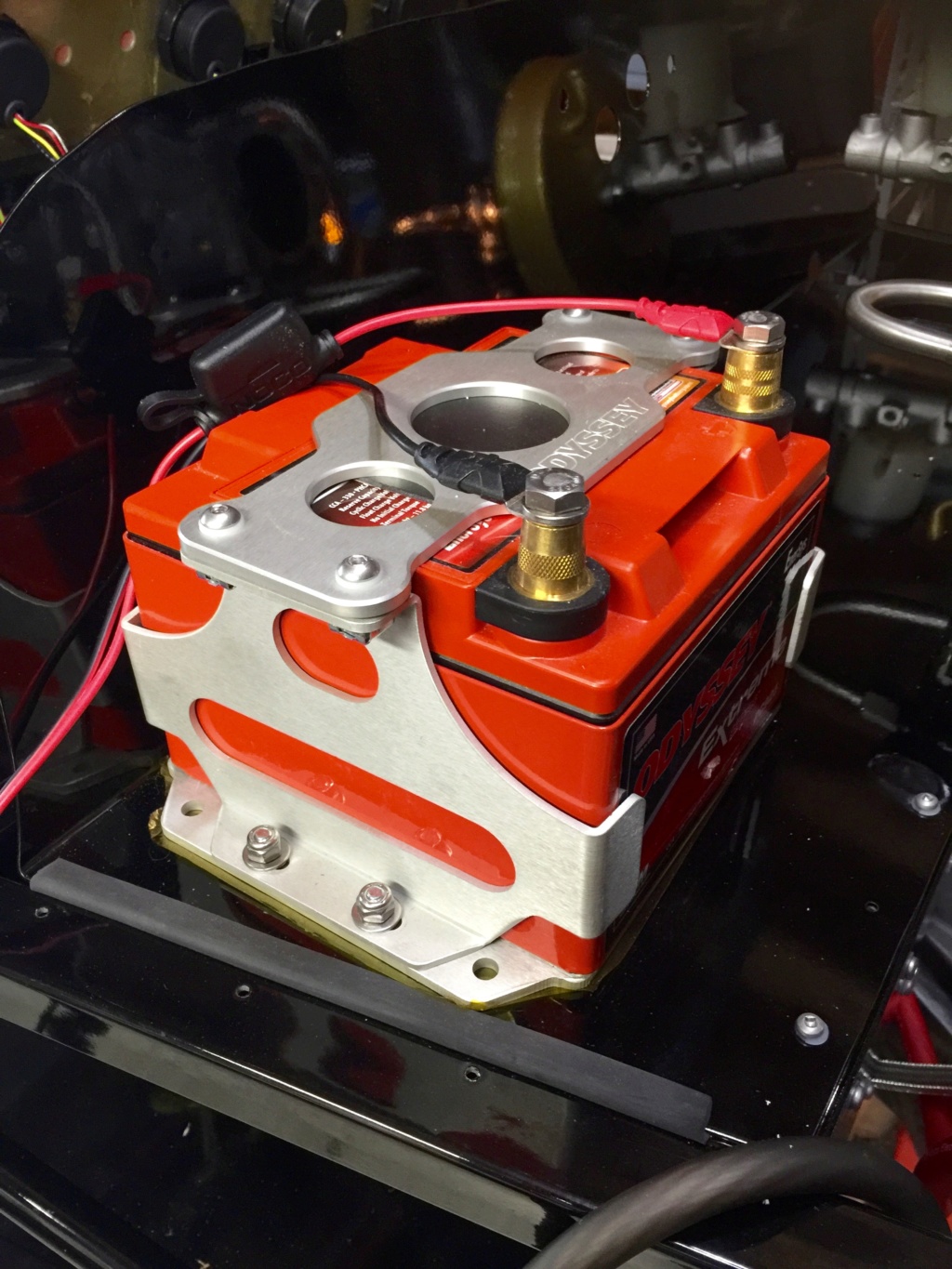
I reinstalled the battery holder and the battery. The wires connected in this picture are for the charger.
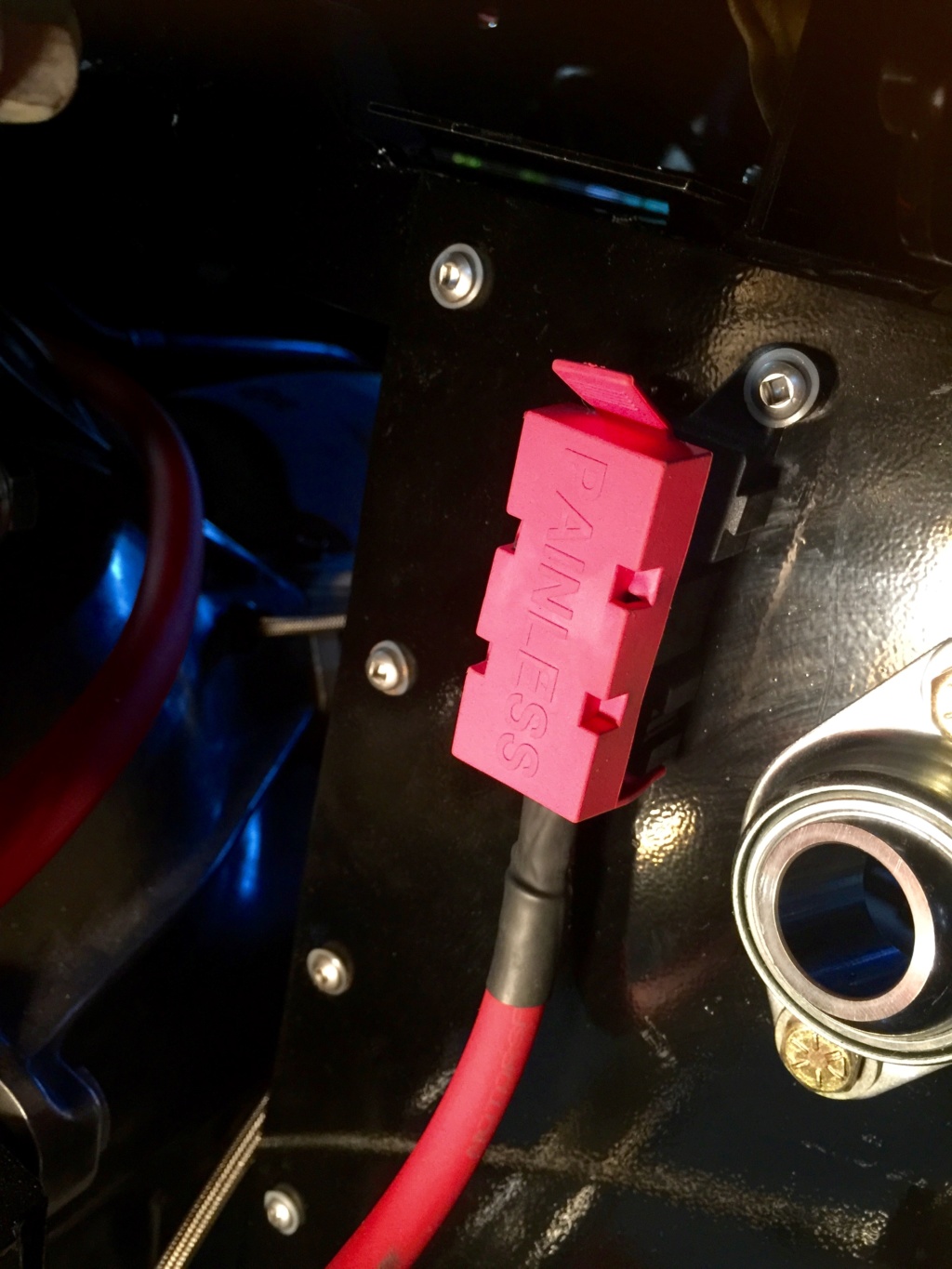
Speaking of wires, I installed this 100A midi fuse in the line from the battery to the alternator. The cable is 6AWG, sourced from prowireusa.com, and it makes the short hop from here...
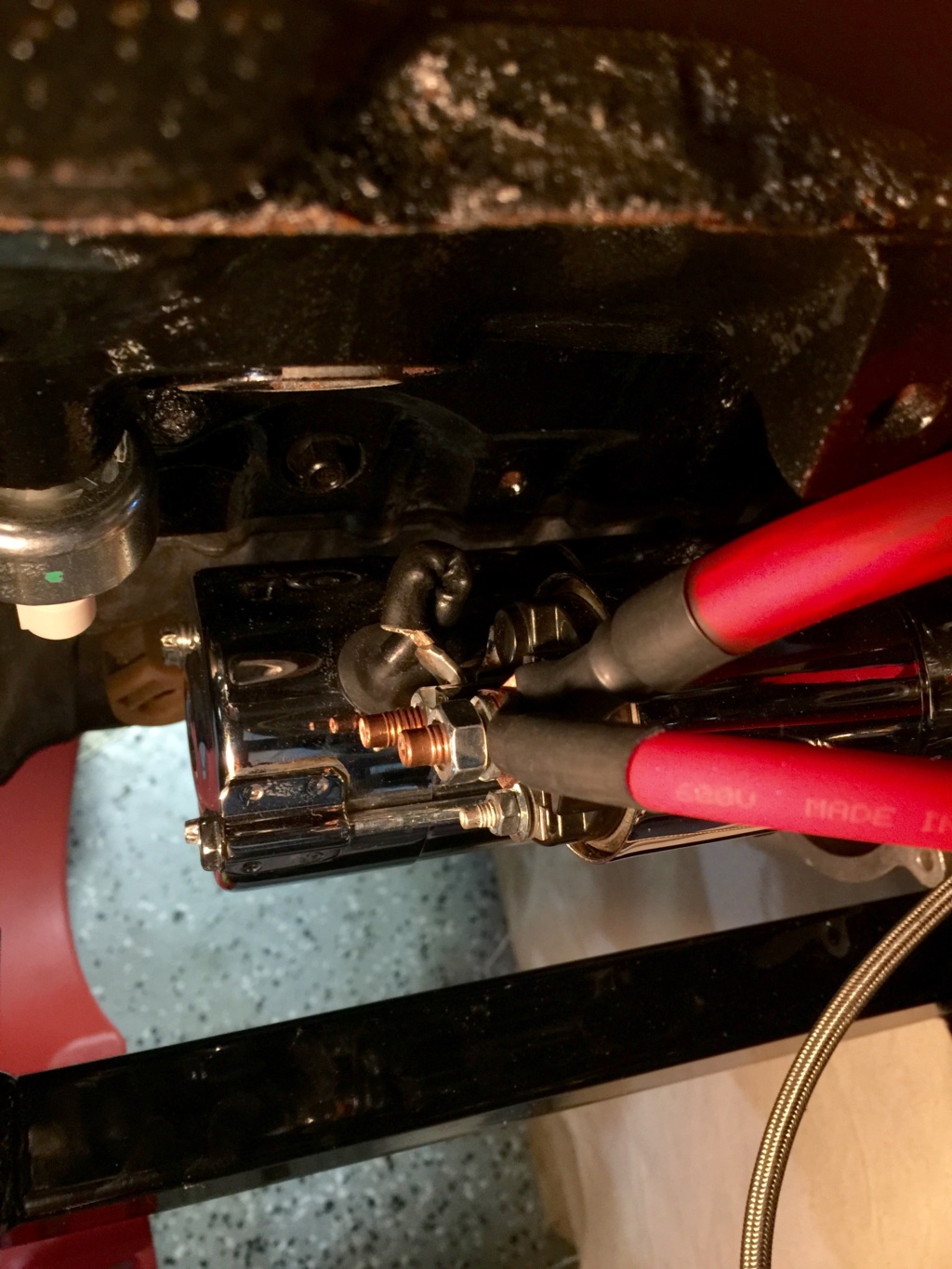
... to the battery terminal on the starter solenoid. The battery cable itself is 2AWG.
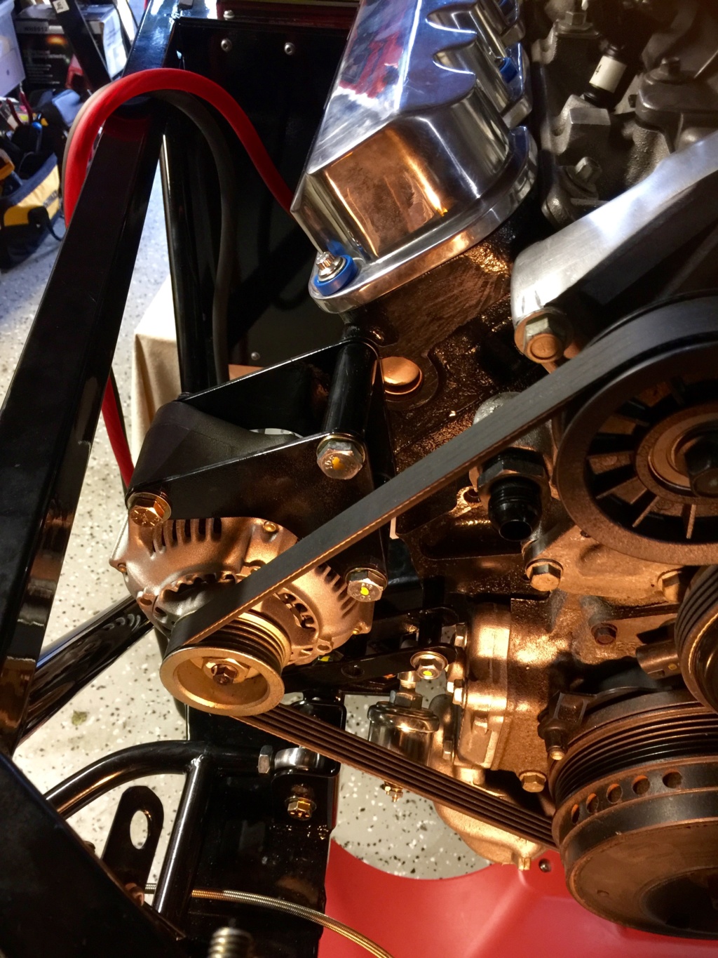
Alternator reinstalled, as yet unconnected. I will be rebuilding the three pin connector, replacing the wires with Tefzel 16 strand and better quality Faston connectors, and wiring directly into my harness to avoid splices.
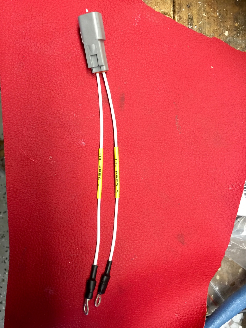
Since I was in an electrical mood I made up this pigtail for the oil pressure sender unit out of 16 strand Tefzel and a Deutsch DT connector.
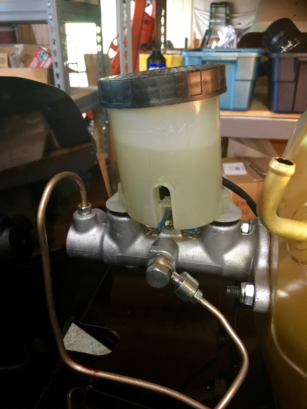
Hey, doesn't that reservoir have brake fluid in it, you ask? Why yes it does. I completed assembly of the brake system, but I had to source a missing part, the banjo and bolt that supply the rear brake system from the side port on the master cylinder. In fact I couldn't find a source for them so I ended up buying an inexpensive brake master cylinder and transferring the banjo, bolt and sealing washers to the other cylinder. I bench bled the master before installing and it did take a while, the better part of an hour in fact, to purge all the air out. I then bled the fronts followed by the rear, making sure the proportioning valve was set to allow full rear brake operation. There were one or two leaks at first but I resolved them systematically. So for now the brakes are done and appear functional.
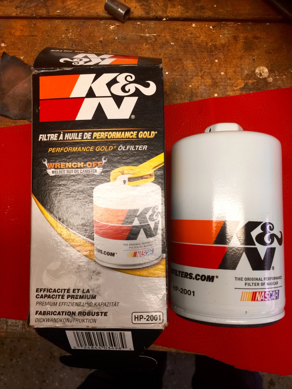
This oil filter is a long canister type and a good fit in the available space. I forgot to mention earlier that I had to install a 45 degree adapter in the oil pressure sender plumbing because it interfered with the alternator installation. Fortunately I had one on hand so I used it and it solved the problem.
After fitting this I filled the engine with 5W30 Royal Purple synthetic engine oil.
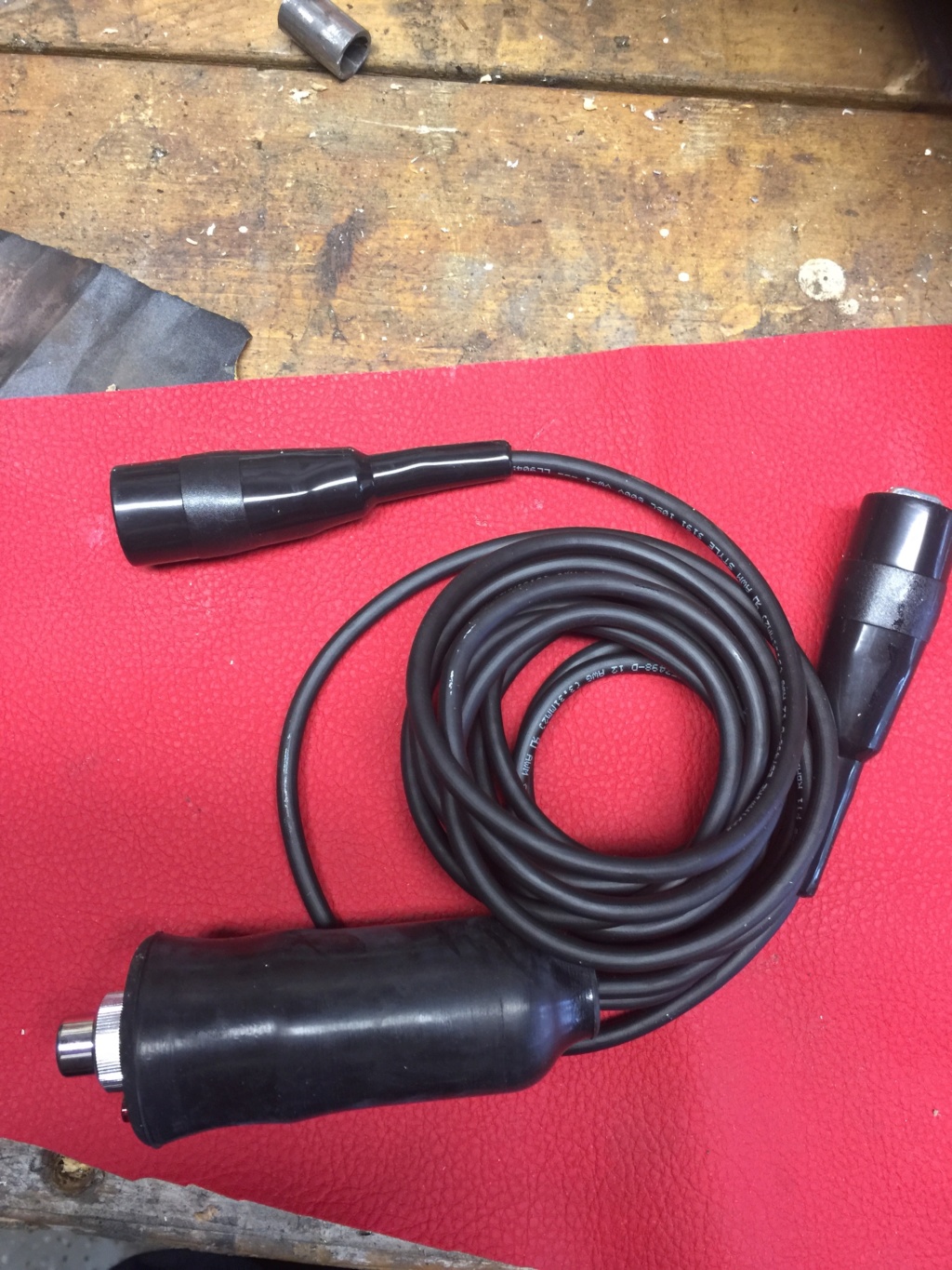
This OTC remote starter button is hefty enough to allow the starter to run for a while without bursting into flames, and it's about 5 feet long.
I'll be able to turn the engine over with this to confirm that we have oil pressure.

Before reinstalling the brake booster I had to put the tray that fits underneath it back in. I opted to secure it with rivnuts, shown here. These are M5s, the smallest size that my rivnut tool can handle.

And here's the offending tool. I haven't been disappointed with Astro gear so far and I have a few odds and ends of theirs, including this rivnut installer and a weatherpack/metripack crimp tool kit.

Powdercoated tray, ready to reinstall under the brake booster.

Here's the brake booster, cleaned up, derusted and repainted before installation. I used left over paint from an Eastwood CAD paint kit. That paint has held up very well in my MG, so I see no reason not to use it here.

I reinstalled the battery holder and the battery. The wires connected in this picture are for the charger.

Speaking of wires, I installed this 100A midi fuse in the line from the battery to the alternator. The cable is 6AWG, sourced from prowireusa.com, and it makes the short hop from here...

... to the battery terminal on the starter solenoid. The battery cable itself is 2AWG.

Alternator reinstalled, as yet unconnected. I will be rebuilding the three pin connector, replacing the wires with Tefzel 16 strand and better quality Faston connectors, and wiring directly into my harness to avoid splices.

Since I was in an electrical mood I made up this pigtail for the oil pressure sender unit out of 16 strand Tefzel and a Deutsch DT connector.

Hey, doesn't that reservoir have brake fluid in it, you ask? Why yes it does. I completed assembly of the brake system, but I had to source a missing part, the banjo and bolt that supply the rear brake system from the side port on the master cylinder. In fact I couldn't find a source for them so I ended up buying an inexpensive brake master cylinder and transferring the banjo, bolt and sealing washers to the other cylinder. I bench bled the master before installing and it did take a while, the better part of an hour in fact, to purge all the air out. I then bled the fronts followed by the rear, making sure the proportioning valve was set to allow full rear brake operation. There were one or two leaks at first but I resolved them systematically. So for now the brakes are done and appear functional.

This oil filter is a long canister type and a good fit in the available space. I forgot to mention earlier that I had to install a 45 degree adapter in the oil pressure sender plumbing because it interfered with the alternator installation. Fortunately I had one on hand so I used it and it solved the problem.
After fitting this I filled the engine with 5W30 Royal Purple synthetic engine oil.

This OTC remote starter button is hefty enough to allow the starter to run for a while without bursting into flames, and it's about 5 feet long.
I'll be able to turn the engine over with this to confirm that we have oil pressure.
 Re: Classic R #27 Build - Final Assembly - Part 2
A handful of test videos from this weekend:
Turning over the engine on the starter after rotating it by hand first. Plugs out, oil in, squirt of oil in each pot, remote starter and battery connected. There was no smoke and no odd noises, and the starter engaged smoothly so I conclude that I will not need to shim it after all. All seems ok so far.
First test of the Speedhut gauges. I selected the voltmeter since it's an easy hookup and doesn't require a running engine. I wanted to see it do the startup dance. They do make a bit of a racket.
Finally - and this was the point of the whole exercise - a confirmation that the engine can develop oil pressure when it turns over. Since this was a used engine that has sat for at least three years I have been anxious to start checking it out (beyond the leakdown test I did almost three years ago). I wasn't sure if I was going to have to prime the oil pump which would have required removing the oil filter bracket.
 Re: Classic R #27 Build - Final Assembly - Part 2
This weekend I wrestled with getting the fuse and relay panels roughed in. It required a lot of aluminum fabrication. My original plan was to install the panels on a hinge so that they would drop down into the passenger footwell for easy access after the scuttle had been installed, but the dimensions wouldn't work. I'd opted a while back to use the Bussman weatherproof fuse boxes that have 10 rows of locations for both fuses and relays, and my schematic has enough circuits that it needs three of them. It may seem like overkill but I'm fussy about fire and I don't want to be dealing with a lot of overloaded switches and wiring. So I worked on a new plan to fit the three boxes.
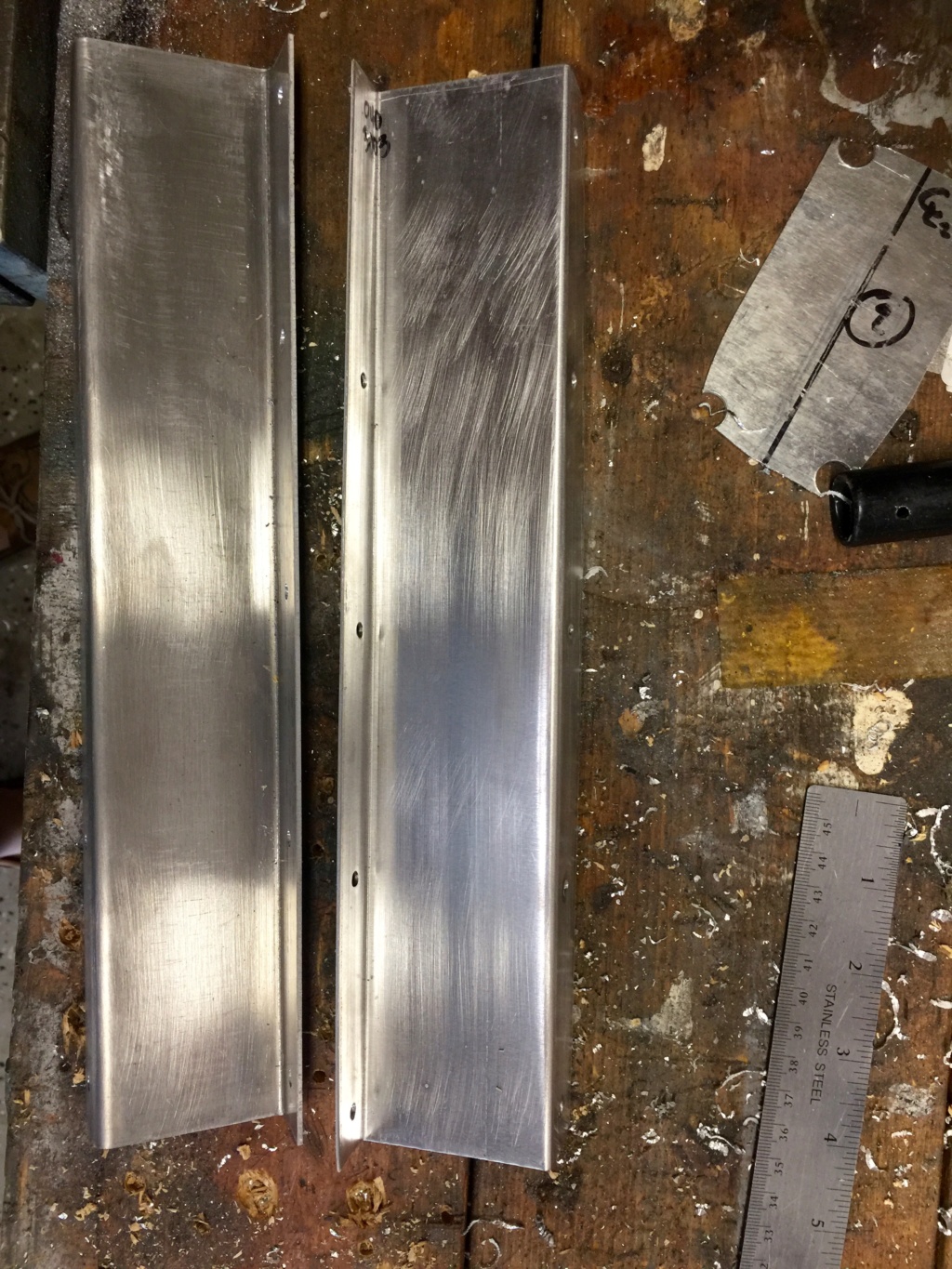
Two brackets, 2 1/4" high to mount the panel to. This will recess the boxes inside the scuttle and away from the passenger compartment knee area.
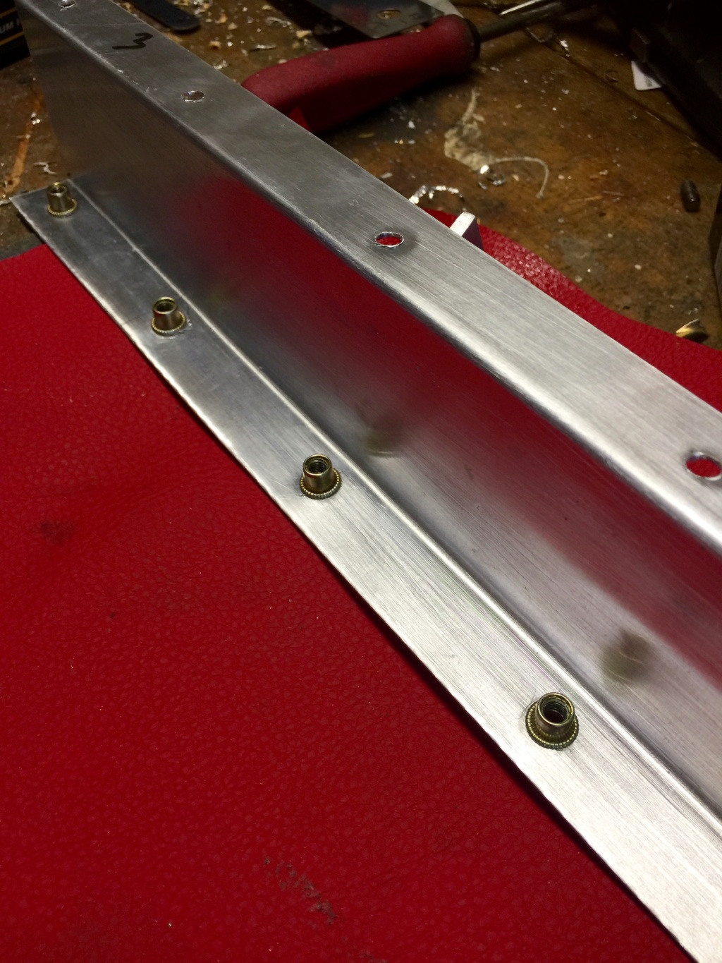
Front bracket gets a row of rivnuts along the bottom edge.
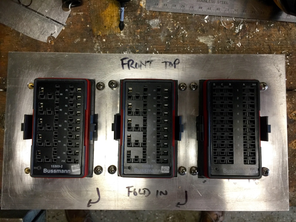
Fuse and relay panel with cutouts for the Bussman boxes. It's not super neat unfortunately. I find this sort of work hard to keep under control. The cutouts were made with a hand nibbler.
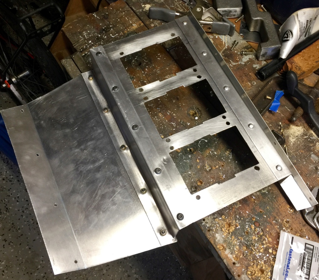
And magically it's done because I forgot to take a lot of photos en route. I'm proud of the riveting work. It's the first time I've tried it and it worked out ok after a few practice shots on some scraps of 16 gauge 6061 but it does call for enormous care and concentration. Dismantled, (except for the riveted parts) all of the panel parts will fit in the powdercoating oven for finishing later.
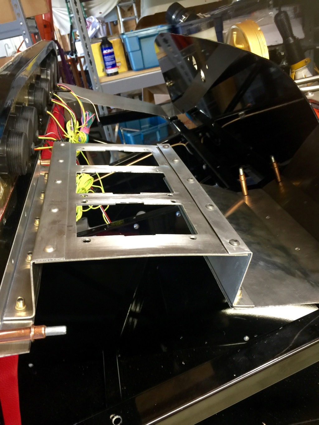
Here's the panel roughed in on the passenger side. It needs a bit of cleanup especially on the outboard edge where the rear bracket isn't quite at right angles to the panel but you get the idea.
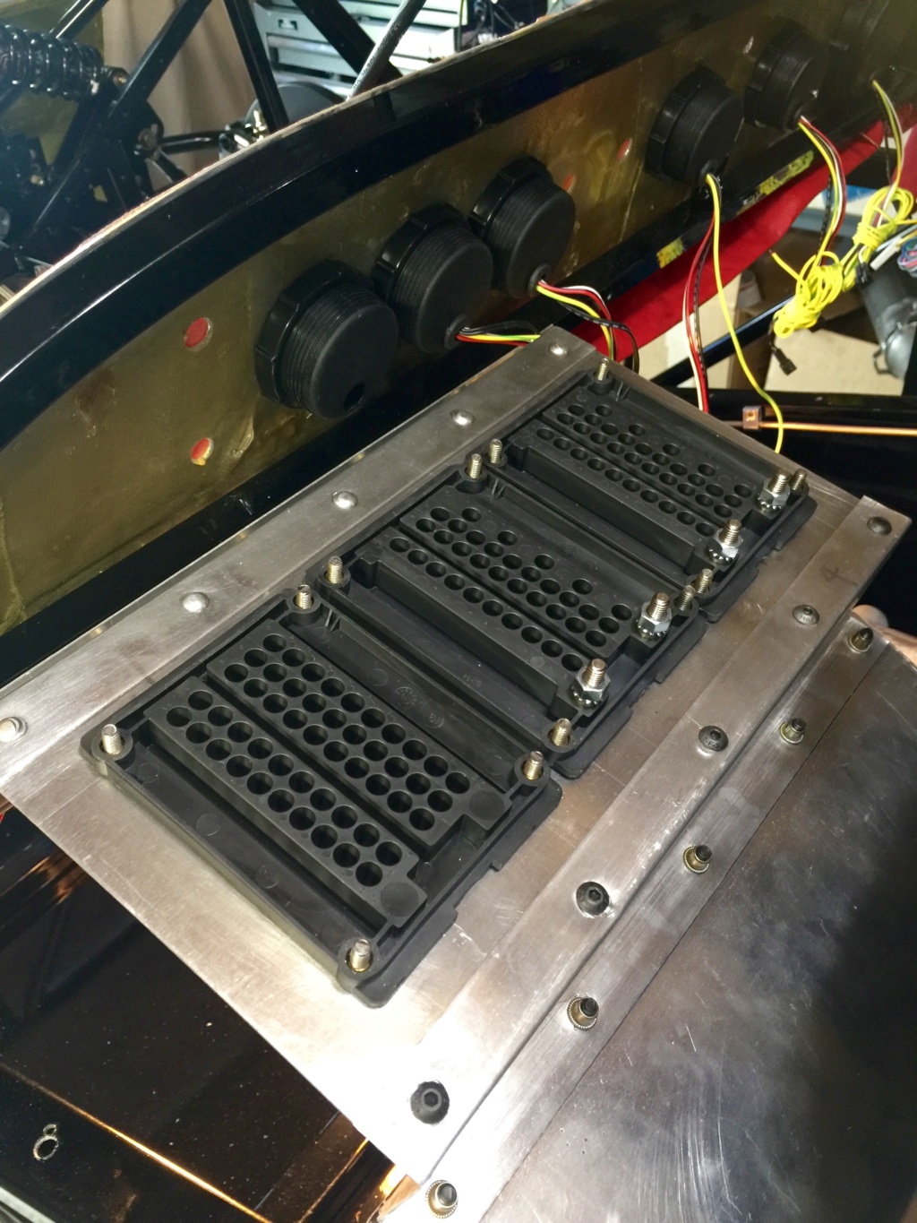
Bussman boxes installed for a trial run in place.
I also spent some time going over the schematic and checking the engine harness. I found out that the ECU signals for controlling the fan are not exposed so I've got to come up with some sort of fan controller arrangement. It bothers me that I've already got two temperature senders, one for the the ECU and one for the temperature gauge, but if I'd realized this earlier I would have added another port on the water neck for a third one.
Options: 1) expose the ECU signals and use them. 2) Add another temp sender and single stage controller 3) Find a single stage controller that works off the temperature gauge sender 4) Design something analog or MCU-based to do the job.
I like options 3 and 4.
A bit of rooting around online turned up the Dakota Digital PAC-2750 ($120) which would fit the bill for option 3, and it supports OBD-II if you buy the extra interface (a further $100). It all seems a bit steep just to turn the fan on and off.

It seems like overkill and it's quite big: over 4 inches wide. Where am I going find that kind of room under the scuttle (or in the cabin for that matter, which is where the manual says it is supposed to be mounted). I need something a bit simpler. I may have to design something myself. I've got an MCU running other stuff for the multifunction gauge so this could perhaps be made part of that package if there's enough code space and I/O left.
In other irritating news, two items of interest. First, my engine harness has the wrong fuel injector connectors on it. The L26 3800 has EV6 fuel injectors; mine shipped with multec connectors. I ordered multec to EV6 adapters for now from Racetronix but they shipped the wrong ones. So that's on hold until I can get hold of Racetronix to sort it out, which is proving tough as they're not answering my emails.
I'm leaning towards making a new engine harness over the winter, but I'll start with the kit one and see where it takes me.
The second item of irritation is that the boots on my steering rack have holes in them I noticed a lot of grease on the outside of the boot and on further inspection found two neat perforations on each boot, almost like vampire bites if you've ever had one of those. Vent holes perhaps, to balance the air pressure in the boot when it compresses? Beats me. I don't know if they're supposed to be there or not but I'm sure that would constitute an inspection fail here in PA so they'll need to be replaced. I ordered new ones from Coleman's web site (RP-120-B). More expense and shipping overhead. I hope they don't have the holes too.

Two brackets, 2 1/4" high to mount the panel to. This will recess the boxes inside the scuttle and away from the passenger compartment knee area.

Front bracket gets a row of rivnuts along the bottom edge.

Fuse and relay panel with cutouts for the Bussman boxes. It's not super neat unfortunately. I find this sort of work hard to keep under control. The cutouts were made with a hand nibbler.

And magically it's done because I forgot to take a lot of photos en route. I'm proud of the riveting work. It's the first time I've tried it and it worked out ok after a few practice shots on some scraps of 16 gauge 6061 but it does call for enormous care and concentration. Dismantled, (except for the riveted parts) all of the panel parts will fit in the powdercoating oven for finishing later.

Here's the panel roughed in on the passenger side. It needs a bit of cleanup especially on the outboard edge where the rear bracket isn't quite at right angles to the panel but you get the idea.

Bussman boxes installed for a trial run in place.
I also spent some time going over the schematic and checking the engine harness. I found out that the ECU signals for controlling the fan are not exposed so I've got to come up with some sort of fan controller arrangement. It bothers me that I've already got two temperature senders, one for the the ECU and one for the temperature gauge, but if I'd realized this earlier I would have added another port on the water neck for a third one.
Options: 1) expose the ECU signals and use them. 2) Add another temp sender and single stage controller 3) Find a single stage controller that works off the temperature gauge sender 4) Design something analog or MCU-based to do the job.
I like options 3 and 4.
A bit of rooting around online turned up the Dakota Digital PAC-2750 ($120) which would fit the bill for option 3, and it supports OBD-II if you buy the extra interface (a further $100). It all seems a bit steep just to turn the fan on and off.

It seems like overkill and it's quite big: over 4 inches wide. Where am I going find that kind of room under the scuttle (or in the cabin for that matter, which is where the manual says it is supposed to be mounted). I need something a bit simpler. I may have to design something myself. I've got an MCU running other stuff for the multifunction gauge so this could perhaps be made part of that package if there's enough code space and I/O left.
In other irritating news, two items of interest. First, my engine harness has the wrong fuel injector connectors on it. The L26 3800 has EV6 fuel injectors; mine shipped with multec connectors. I ordered multec to EV6 adapters for now from Racetronix but they shipped the wrong ones. So that's on hold until I can get hold of Racetronix to sort it out, which is proving tough as they're not answering my emails.
I'm leaning towards making a new engine harness over the winter, but I'll start with the kit one and see where it takes me.
The second item of irritation is that the boots on my steering rack have holes in them I noticed a lot of grease on the outside of the boot and on further inspection found two neat perforations on each boot, almost like vampire bites if you've ever had one of those. Vent holes perhaps, to balance the air pressure in the boot when it compresses? Beats me. I don't know if they're supposed to be there or not but I'm sure that would constitute an inspection fail here in PA so they'll need to be replaced. I ordered new ones from Coleman's web site (RP-120-B). More expense and shipping overhead. I hope they don't have the holes too.
 Re: Classic R #27 Build - Final Assembly - Part 2
Nice work!! Great build thread/posts.
rdymond- Posts : 1
Join date : 2016-07-11
 Re: Classic R #27 Build - Final Assembly - Part 2
This week I've been struggling with weeping brake fittings. First the banjo fitting on the master cylinder started weeping after a few days. I replaced the copper washers with new ones but to no avail. Finally I took them off, annealed them, cleaned them and reassembled everything. I hope this has done the trick. The tightening force felt quite different this time so I'm guessing the others were just work hardened and lacked compliance. I'm working through the flares one by one, dismantling, checking for debris/poor seating and then reassembling. It's somewhat depressing but if I work through it methodically I'll be able to sort it out, or so I tell myself. Frankly I dread doing the fuel system - and the cooling system for that matter.
In other news, after considering my options I went with the PAC-2750 fan controller. It's a lot smaller than I expected and I'll find a spot for it, probably under the dash somewhere out of the way.
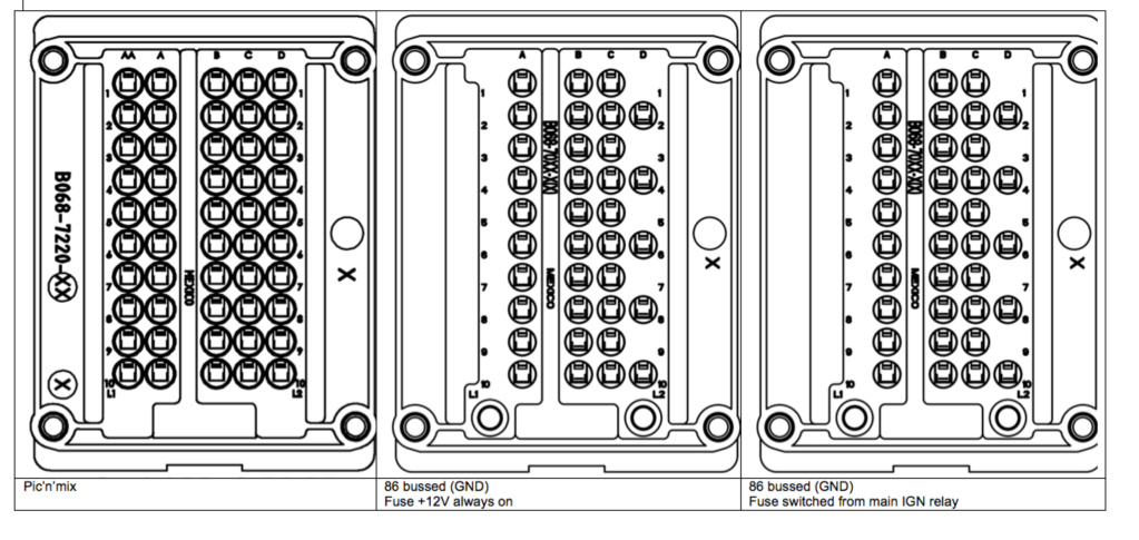
I've also been continuing work on the electrical panel. Using full size images of the three Bussman boxes (copied from the Bussman data sheets and pasted into Word) and my schematic, fuse, relay and wire gauge notes, I laid out the fuse/relay box wiring on tracing paper overlaid on this Bussman box layout sheet. I now know where each fuse and relay will be located. Each box represents a different circuit requirement: Box 1 is bussed and is for always-on circuits. Box 2 is bussed and is for circuits driven off the main relay (ignition-switched circuits). Box 3 is not bussed and is for everything else.
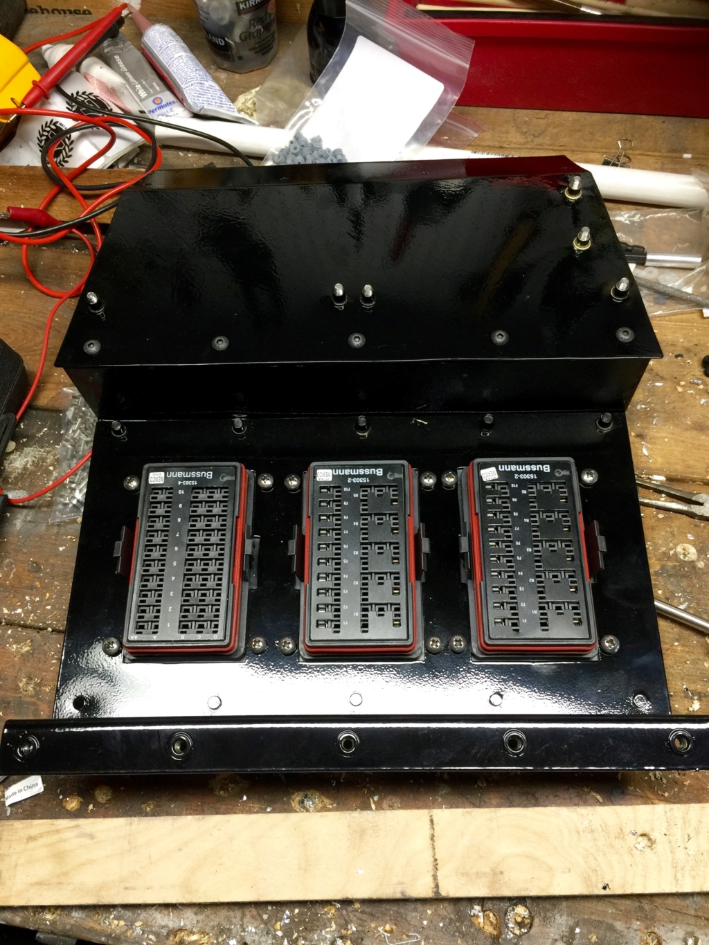
Here's the underside of the panel. This is what's visible inside the passenger side footwell. My powdercoating on these parts is a bit ropey. I seem to have trouble with large surfaces. Thank heavens for rivnuts by the way. Those things are awesome. Oh and if you're a cheapskate like me you'll find that the M5-8.0 rivnut is a twofer - in addition to the M5, it accepts a 10-32 machine screw without argument.
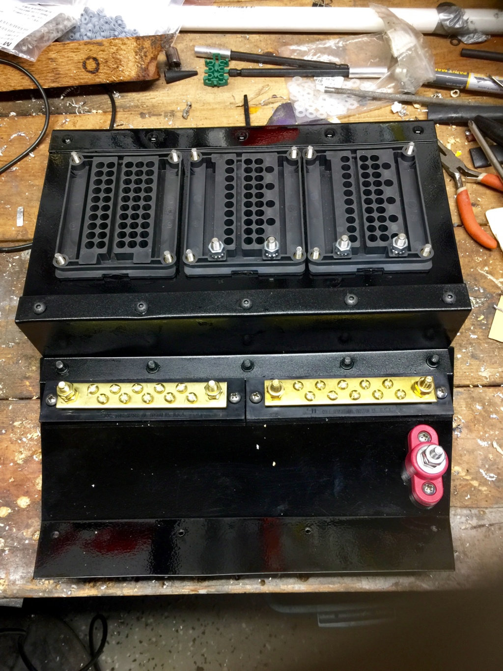
Here's the wiring side. I'll wire the whole thing off the car, terminate the circuits with Deutsch connectors and then install it. That's the final remaining design step I think: to plan the connector needs and locate mounting points for them so that they don't just flap around. The two busbars are for ground distribution.

Closeup of the hot and ground entry points. I planned a single entry point to the panel for the power coming in. I'm considering using a big Anderson connector to interface to the power source but I'm not sure it's really necessary.
My replacement Coleman boots arrived in the mail and they too have the vampire holes in them. I dismantled the rack and removed some excess grease that had accumulated in the boot (so that it won't ooze out of the holes in the boot), then cleaned up and reassembled. Have to live with it I guess.
Finally, Racetronix shipped out the correct fuel injector adapters and I've put them on the injectors to confirm that they fit.
In other news, after considering my options I went with the PAC-2750 fan controller. It's a lot smaller than I expected and I'll find a spot for it, probably under the dash somewhere out of the way.

I've also been continuing work on the electrical panel. Using full size images of the three Bussman boxes (copied from the Bussman data sheets and pasted into Word) and my schematic, fuse, relay and wire gauge notes, I laid out the fuse/relay box wiring on tracing paper overlaid on this Bussman box layout sheet. I now know where each fuse and relay will be located. Each box represents a different circuit requirement: Box 1 is bussed and is for always-on circuits. Box 2 is bussed and is for circuits driven off the main relay (ignition-switched circuits). Box 3 is not bussed and is for everything else.

Here's the underside of the panel. This is what's visible inside the passenger side footwell. My powdercoating on these parts is a bit ropey. I seem to have trouble with large surfaces. Thank heavens for rivnuts by the way. Those things are awesome. Oh and if you're a cheapskate like me you'll find that the M5-8.0 rivnut is a twofer - in addition to the M5, it accepts a 10-32 machine screw without argument.

Here's the wiring side. I'll wire the whole thing off the car, terminate the circuits with Deutsch connectors and then install it. That's the final remaining design step I think: to plan the connector needs and locate mounting points for them so that they don't just flap around. The two busbars are for ground distribution.

Closeup of the hot and ground entry points. I planned a single entry point to the panel for the power coming in. I'm considering using a big Anderson connector to interface to the power source but I'm not sure it's really necessary.
My replacement Coleman boots arrived in the mail and they too have the vampire holes in them. I dismantled the rack and removed some excess grease that had accumulated in the boot (so that it won't ooze out of the holes in the boot), then cleaned up and reassembled. Have to live with it I guess.
Finally, Racetronix shipped out the correct fuel injector adapters and I've put them on the injectors to confirm that they fit.
 Re: Classic R #27 Build - Final Assembly - Part 2
Over the weekend I powdercoated and installed the heater mounting brackets. I wanted to get the heater in place because it has a big impact on the amount of free space for mounting some of the remaining electrical components. The heater's tacked in with clecos for now.
I also crimped and wired in the Anderson connectors for the battery. I may remove them later but for debugging the wiring I think it will be useful to have a quick disconnect on the fuse panel. The hydraulic crimp tool I bought did a fine job on the Anderson connectors: I think it was a No. 35 die that I ended up using.
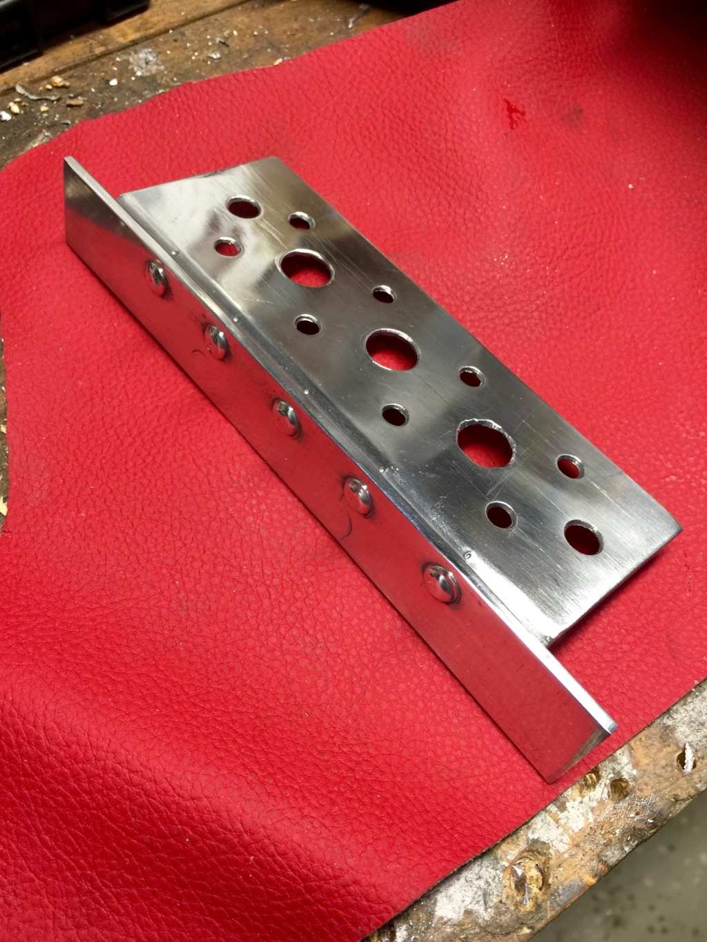
Some of the controls (ignition, start, fuel pump disable, gauge backlight brightness and multifunction display select) are going to be mounted out of sight behind the dash. I started playing with some ideas for a switch panel. This was supposed to be a prototype but I like it even though it's a bit rough. It's a piece of 16 gauge aluminum folded and riveted to a bar that will attach behind the dash, in front of the heater. I got sidetracked into playing with my (ancient) polishing kit. I didn't take time to polish all the deep marks out of the metal, just a perfunctory shine-up as an alternative to powdercoating since this is supposed to be a prototype. I got to play with more aircraft rivets and I'm still getting the hang of how to use that riveting tool, but I love the results. By the way, the powdercoating parts pile is diminishing rapidly. I'm pretty much down to the throttle parts, coolant overflow tank bracket and the brackets for the coolant fan then I can knock down the powdercoat station in the shop and clean up back there.
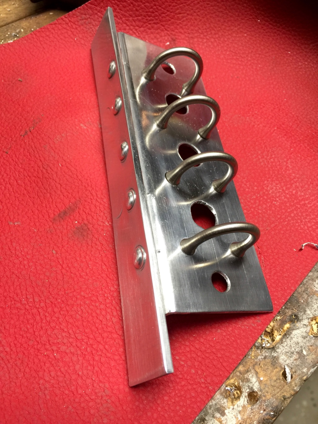
I'd bought these "NASA-style" switch guards a long time ago just in case. I like the look. They complement the Honeywell Micro Switches I'll be using.
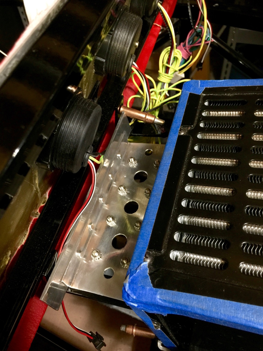
This is roughly where it will mount, up under the dash so it's out of sight. I don't really want all these switches cluttering up the cabin area. Two more holes to measure, mark and drill. I have the switches already and will mount them after the remaining holes are dealt with.
I also crimped and wired in the Anderson connectors for the battery. I may remove them later but for debugging the wiring I think it will be useful to have a quick disconnect on the fuse panel. The hydraulic crimp tool I bought did a fine job on the Anderson connectors: I think it was a No. 35 die that I ended up using.

Some of the controls (ignition, start, fuel pump disable, gauge backlight brightness and multifunction display select) are going to be mounted out of sight behind the dash. I started playing with some ideas for a switch panel. This was supposed to be a prototype but I like it even though it's a bit rough. It's a piece of 16 gauge aluminum folded and riveted to a bar that will attach behind the dash, in front of the heater. I got sidetracked into playing with my (ancient) polishing kit. I didn't take time to polish all the deep marks out of the metal, just a perfunctory shine-up as an alternative to powdercoating since this is supposed to be a prototype. I got to play with more aircraft rivets and I'm still getting the hang of how to use that riveting tool, but I love the results. By the way, the powdercoating parts pile is diminishing rapidly. I'm pretty much down to the throttle parts, coolant overflow tank bracket and the brackets for the coolant fan then I can knock down the powdercoat station in the shop and clean up back there.

I'd bought these "NASA-style" switch guards a long time ago just in case. I like the look. They complement the Honeywell Micro Switches I'll be using.

This is roughly where it will mount, up under the dash so it's out of sight. I don't really want all these switches cluttering up the cabin area. Two more holes to measure, mark and drill. I have the switches already and will mount them after the remaining holes are dealt with.
 Similar topics
» Classic R #27 Build - Final Assembly - Part 6
» Classic R #27 Build - Final Assembly - Part 3
» Classic R #27 Build - Final Assembly - Part 4
» Classic R #27 Build - Final Assembly - Part 5
» Classic R #27 Build - Final Assembly
» Classic R #27 Build - Final Assembly - Part 3
» Classic R #27 Build - Final Assembly - Part 4
» Classic R #27 Build - Final Assembly - Part 5
» Classic R #27 Build - Final Assembly
Page 1 of 1
Permissions in this forum:
You cannot reply to topics in this forum