Classic R #27 Build - Final Assembly
2 posters
Page 1 of 1

Classic R #27 Build - Final Assembly
![]() by comled Fri Jul 06, 2018 8:23 pm
by comled Fri Jul 06, 2018 8:23 pm
The big day has finally arrived when I get to put all this lovely stuff back together and make a car out of it.
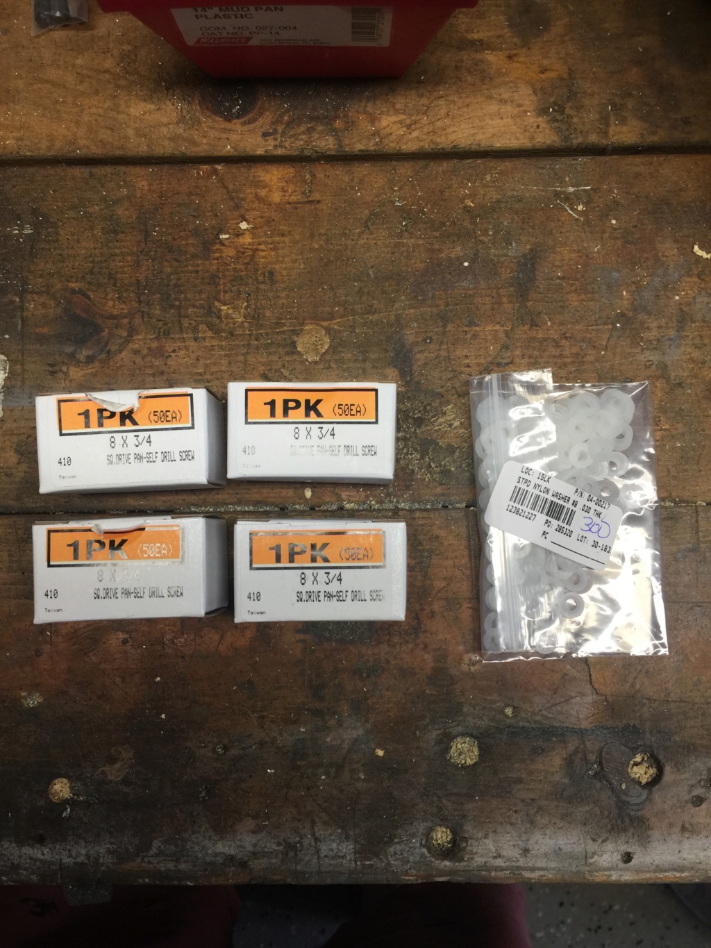
I've got enough hardware on hand to mount the floor pans and the drivers side footwell panel. From a previous lesson learned I'm using hardware from a reputable supplier.

I found putting the frame on its side made access easier than trying to work on a completely inverted frame.

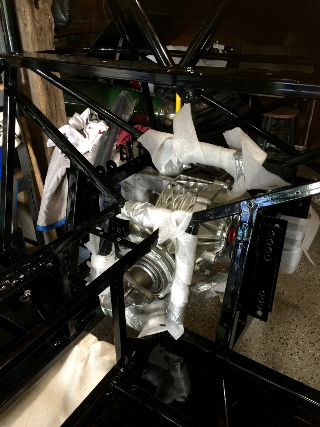
First order of business was to make good a couple of spots on the frame where it had been resting on the cart while being powdercoated. I used POR-15 to touch in a couple of spots that weren't done, including up inside the transmission crossmember.

With that sorted out, the floors could be remounted. Each screw hole gets a 8x3/4 self drill stainless screw, a nylon washer and a dab of antisieze compound.

A view along those floor pan screws.

Easy to remount the pedals now rather than when the frame is resting on the build table.

Drivers side footwell panel needs to be powdercoated before reinstallation. I had to give it two coats because the first wouldn't flow right. I think the coating was too thin.

Footwell panel installed along with the clutch master cylinder.

Brake pedal linkage also has to be cleaned up and powdercoated before installation.

Assembled linkage from the engine bay side.

Clutch and brake linkages from the driver footwell side. Don't forget the locknuts on the brake linkage heim joints.
All in all it was a productive day. There's something enjoyable about putting a freshly powdercoated part, still warm from the oven, into the final assembly. Plenty more still to do.
-Dave
I've got enough hardware on hand to mount the floor pans and the drivers side footwell panel. From a previous lesson learned I'm using hardware from a reputable supplier.
I found putting the frame on its side made access easier than trying to work on a completely inverted frame.
First order of business was to make good a couple of spots on the frame where it had been resting on the cart while being powdercoated. I used POR-15 to touch in a couple of spots that weren't done, including up inside the transmission crossmember.
With that sorted out, the floors could be remounted. Each screw hole gets a 8x3/4 self drill stainless screw, a nylon washer and a dab of antisieze compound.
A view along those floor pan screws.
Easy to remount the pedals now rather than when the frame is resting on the build table.
Drivers side footwell panel needs to be powdercoated before reinstallation. I had to give it two coats because the first wouldn't flow right. I think the coating was too thin.
Footwell panel installed along with the clutch master cylinder.
Brake pedal linkage also has to be cleaned up and powdercoated before installation.
Assembled linkage from the engine bay side.
Clutch and brake linkages from the driver footwell side. Don't forget the locknuts on the brake linkage heim joints.
All in all it was a productive day. There's something enjoyable about putting a freshly powdercoated part, still warm from the oven, into the final assembly. Plenty more still to do.
-Dave

comled- Posts : 179
Join date : 2015-10-07
Location : New Hope, PA -

Re: Classic R #27 Build - Final Assembly
![]() by comled Thu Jul 12, 2018 11:38 pm
by comled Thu Jul 12, 2018 11:38 pm
Minor progress to report today.
Two more panels came back from the powdercoaters. Pictures to follow.
Yesterday I powdercoated the brake light switch bracket at home and today I decided to address the brake light switch. I wasn't happy with the grade of wire or connector, nor was I happy with the quality of the attachment of the wires to the switch contacts.

Here's the before picture, as the switch was when it was fresh out of the box. Those connections won't hold up in the long term.

Here's the modified switch. The old wiring was abraded off using a Dremel and the connectors cleaned up. New lengths of 14ga teflon wire have been attached, soldered on and heatshrink tubing applied to each terminal. Then a larger diameter piece of heatshrink tubing was placed over the switch body and shrunk into place.
The switch read 64 ohms when closed, which is a bit on the high side. Some IPA squirted down the side of the plunger helped to clean the contacts and reduce the impedance down to a more respectable 0.2 ohms closed.

The final step for today was to pot the teflon wires with RTV sealant and leave to cure for 24 hours. This should create a far more robust assembly to attach to the brake system.
The final step will be to crimp on a 2 pin Deutsch DT connector. I'm trying to standardize on Deutsch connectors throughout the build and I was able to withstand the temptation to use a 2 pin Delphi Weatherpack connector that I had on hand just to get the job done. Better to wait and do things the way I want them. In terms of brake wiring this means that the brake fluid warning switch will also get a minor remake and a standardized connector. More on that another day.
-Dave
Two more panels came back from the powdercoaters. Pictures to follow.
Yesterday I powdercoated the brake light switch bracket at home and today I decided to address the brake light switch. I wasn't happy with the grade of wire or connector, nor was I happy with the quality of the attachment of the wires to the switch contacts.
Here's the before picture, as the switch was when it was fresh out of the box. Those connections won't hold up in the long term.
Here's the modified switch. The old wiring was abraded off using a Dremel and the connectors cleaned up. New lengths of 14ga teflon wire have been attached, soldered on and heatshrink tubing applied to each terminal. Then a larger diameter piece of heatshrink tubing was placed over the switch body and shrunk into place.
The switch read 64 ohms when closed, which is a bit on the high side. Some IPA squirted down the side of the plunger helped to clean the contacts and reduce the impedance down to a more respectable 0.2 ohms closed.
The final step for today was to pot the teflon wires with RTV sealant and leave to cure for 24 hours. This should create a far more robust assembly to attach to the brake system.
The final step will be to crimp on a 2 pin Deutsch DT connector. I'm trying to standardize on Deutsch connectors throughout the build and I was able to withstand the temptation to use a 2 pin Delphi Weatherpack connector that I had on hand just to get the job done. Better to wait and do things the way I want them. In terms of brake wiring this means that the brake fluid warning switch will also get a minor remake and a standardized connector. More on that another day.
-Dave
comled- Posts : 179
Join date : 2015-10-07
Location : New Hope, PA -
Re: Classic R #27 Build - Final Assembly
![]() by comled Sat Jul 21, 2018 9:04 am
by comled Sat Jul 21, 2018 9:04 am
Managed to get the differential reinstalled. It's tricky and I'd forgotten how I did it the first time. This time around the work is made more difficult by having to protect the finish on the frame. Scott suggested putting the pinion in as far to one side as possible, then getting the short ear side of the pumpkin through the frame, and finally the long ear side. It's a grunt getting it in but that was the way it ended up working out. It didn't help that I lost one of the bolts and ran to Fastenal to get another one, found the store had closed down, went to the next nearest one, got the bolt, got home and then found the missing bolt at the bottom of the laundry basket where it had fallen out of the pocket of my shorts the night before.
The differential drain and fill plugs require a 10mm hex bit and mine are particularly tight and hard to move. I did finally shift the fill plug but the drain plug won't move, so I've ordered half inch square drive hex bits to up my game. May as well sort all this out before the driveshafts get installed and limit access.
I also got the driver's side rear suspension arms back in over a couple of evenings this week. I hope to complete the driver's side hub and driveshaft installation over the weekend.
comled- Posts : 179
Join date : 2015-10-07
Location : New Hope, PA -
Re: Classic R #27 Build - Final Assembly
![]() by comled Sun Jul 22, 2018 10:51 pm
by comled Sun Jul 22, 2018 10:51 pm
I made quite a lot of progress this weekend on getting the rear end reassembled. The rear suspension, driveshafts, rear calipers and brake discs are back on the car. I'm missing a couple of cone washers so need to order more.

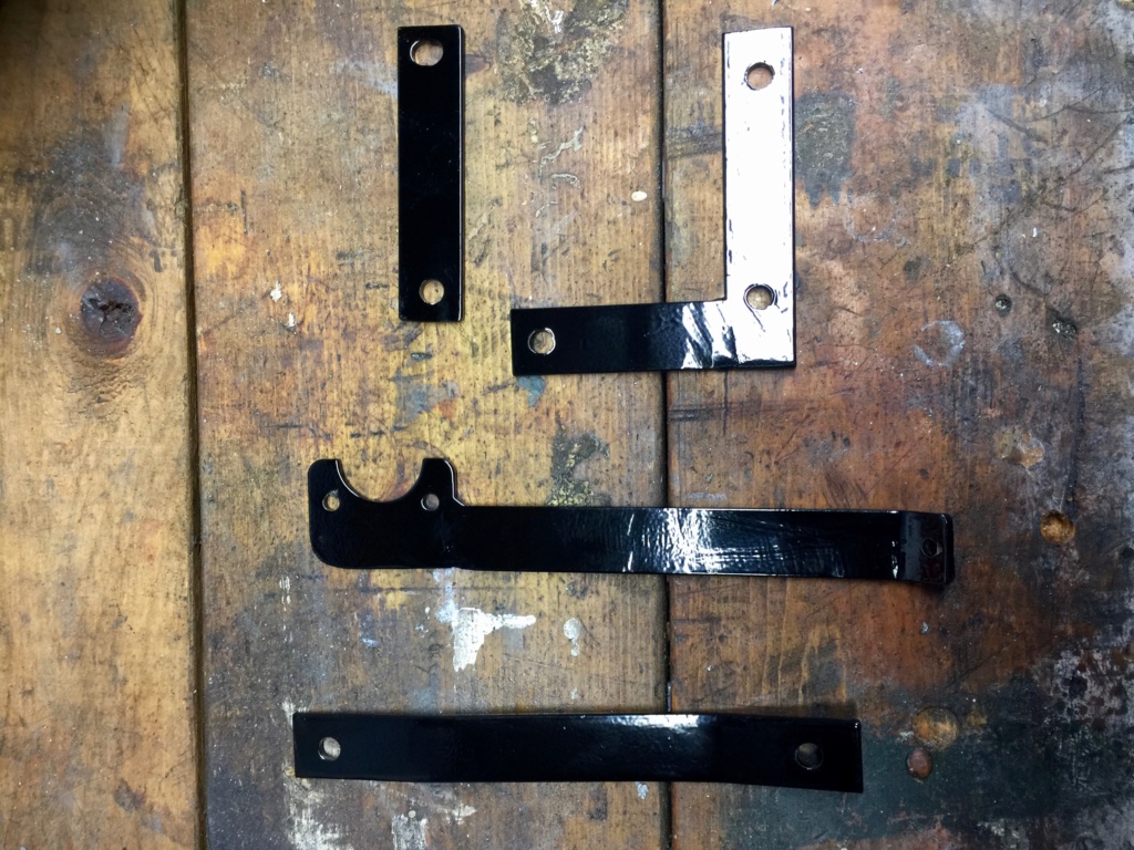
The powdercoating oven was running most of today. I coated the caliper and parking brake brackets...
... these small rear brake parts plus the custom bracket that runs over the diff...

... and finally this parking brake lever bracket so I can get the parking brake system reinstalled.

Here's the state of things at the end of Sunday.
The powdercoating oven was running most of today. I coated the caliper and parking brake brackets...
... these small rear brake parts plus the custom bracket that runs over the diff...
... and finally this parking brake lever bracket so I can get the parking brake system reinstalled.
Here's the state of things at the end of Sunday.
comled- Posts : 179
Join date : 2015-10-07
Location : New Hope, PA -
Re: Classic R #27 Build - Final Assembly
![]() by comled Wed Jul 25, 2018 7:58 am
by comled Wed Jul 25, 2018 7:58 am

While installing the rear spindles I noticed that the end of the bolts were perilously close to the CV joints on the drive shafts. I opted to replace each 3 1/2" long bolt with a 5/8-18 x 3" version. Fastenal had them in stock. The nyloc nut still engages fully with the thread but there's more clearance between the end of the bolt and the CV joint. With bolts in hand I completed the installation of the spindles. I used thread locker on the top eye bolt and on its associated lock nut.
Also installed the rear brake pads.
comled- Posts : 179
Join date : 2015-10-07
Location : New Hope, PA -
Re: Classic R #27 Build - Final Assembly
![]() by comled Sun Jul 29, 2018 9:38 am
by comled Sun Jul 29, 2018 9:38 am
I had a big day of reassembly on Saturday with a lot of small things accomplished.


I'd removed the magnetic speed sensors from the rear hubs because I'm not expecting to use them. That left a gaping hole in each of the hubs. I modeled and then 3D printed these plugs that fill the openings left by the sensor.
I installed the plugs with a dab of silicon gasket sealant and threadlocker on the hex cap screw that holds it in place.
The powdercoating oven also got a workout on Saturday. These are the rest of the braking system parts plus the fuel pump and fuel regulator brackets that I'll be installing. I hope to get most of the rear end put together by Sunday night.

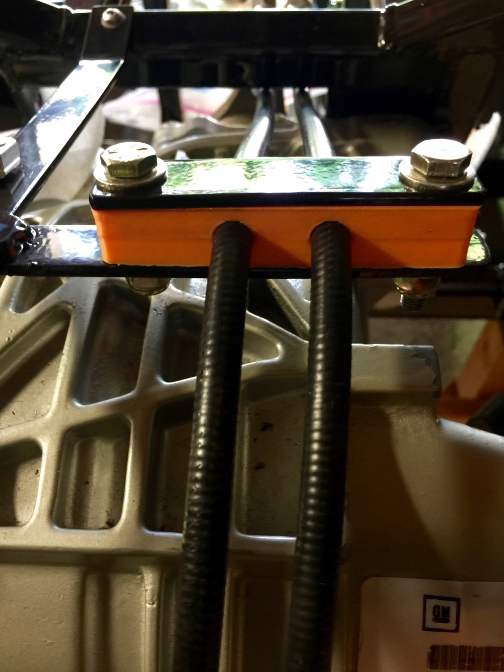
I'd also made and printed these guide blocks for the parking brake cables. They help prevent the cables from flapping about unconstrained behind the fuel tank. Here they are installed with one of the powdercoated parts.
I completed reassembly of the rear brakes and parking brake.

I installed my first fluid in the car. That feels like progress. I drained the diff and cleaned up the drain plug. There wasn't much left in it but may I figured I may as well start with from as fresh a state as possible. I refilled it through the side hole. The instructions say to use 1 quart of oil but it actually needs 1.15 quarts. If you add separate friction modifier then the volume probably works out correctly but I'm using a Valvoline nonsynthetic that's defined for limited slip use, so it already has the friction modifier mixed in. Back to the autoparts store on Monday morning.
With all the braking and hub stuff done I started on the fuel tank. I had to finish up some adjustments on the fuel gauge sender to correct the length. Now I get full resistance travel off the sender. The tank's back in and bolted down and next up I'll install the regulator, pump and filters.
I'd removed the magnetic speed sensors from the rear hubs because I'm not expecting to use them. That left a gaping hole in each of the hubs. I modeled and then 3D printed these plugs that fill the openings left by the sensor.
I installed the plugs with a dab of silicon gasket sealant and threadlocker on the hex cap screw that holds it in place.
The powdercoating oven also got a workout on Saturday. These are the rest of the braking system parts plus the fuel pump and fuel regulator brackets that I'll be installing. I hope to get most of the rear end put together by Sunday night.
I'd also made and printed these guide blocks for the parking brake cables. They help prevent the cables from flapping about unconstrained behind the fuel tank. Here they are installed with one of the powdercoated parts.
I completed reassembly of the rear brakes and parking brake.
I installed my first fluid in the car. That feels like progress. I drained the diff and cleaned up the drain plug. There wasn't much left in it but may I figured I may as well start with from as fresh a state as possible. I refilled it through the side hole. The instructions say to use 1 quart of oil but it actually needs 1.15 quarts. If you add separate friction modifier then the volume probably works out correctly but I'm using a Valvoline nonsynthetic that's defined for limited slip use, so it already has the friction modifier mixed in. Back to the autoparts store on Monday morning.
With all the braking and hub stuff done I started on the fuel tank. I had to finish up some adjustments on the fuel gauge sender to correct the length. Now I get full resistance travel off the sender. The tank's back in and bolted down and next up I'll install the regulator, pump and filters.
comled- Posts : 179
Join date : 2015-10-07
Location : New Hope, PA -
Re: Classic R #27 Build - Final Assembly
![]() by comled Mon Jul 30, 2018 11:17 pm
by comled Mon Jul 30, 2018 11:17 pm
The rear end's almost complete for now other than topping up the diff and installing some brake line clips. Time to get the engine and transmission ready to put back in the car.

I followed the instructions for prepping the slave cylinder, using a 1/8 drive pin punch to push the roll pin out of the way so that the stock union can be remoted.

With the new hose in position the roll pin can be driven back in. Make sure it goes through both sides of the housing.

The bleed screw is easily removed using a 7/16" open ended wrench. The replacement bleed line screws directly into the slave cylinder.

A view of the completed slave cylinder assembly.

To work out where to drill the hole for the bleed line, temporarily install the slave cylinder on the transmission without the hoses. Estimate where the line would pass through the bellhousing and mark on the inside with a pen and then centerpunch it.

Working from inside the bellhousing, pilot drill the hole...

... and then open the hole out with a step drill. The more accurate the location of the hole the smaller it can be (up to a point).

Mine ended up being about 5/8". Not too bad.

Here's the slave cylinder temporarily positioned to check the routing of the hoses. The hose that runs to the clutch master cylinder exits the bellhousing though a spare hole on the drivers side of the housing.
There were no bolts in my clutch kit for mounting the clutch slave cylinder to the transmission. I determined empirically that the required bolts are M6-1.0 x 25mm and I picked some up at Fastenal today. I also ordered M12 standard thread bolts in grade 10.9 for mounting the bellhousing to the transmission.
I followed the instructions for prepping the slave cylinder, using a 1/8 drive pin punch to push the roll pin out of the way so that the stock union can be remoted.
With the new hose in position the roll pin can be driven back in. Make sure it goes through both sides of the housing.
The bleed screw is easily removed using a 7/16" open ended wrench. The replacement bleed line screws directly into the slave cylinder.
A view of the completed slave cylinder assembly.
To work out where to drill the hole for the bleed line, temporarily install the slave cylinder on the transmission without the hoses. Estimate where the line would pass through the bellhousing and mark on the inside with a pen and then centerpunch it.
Working from inside the bellhousing, pilot drill the hole...
... and then open the hole out with a step drill. The more accurate the location of the hole the smaller it can be (up to a point).
Mine ended up being about 5/8". Not too bad.
Here's the slave cylinder temporarily positioned to check the routing of the hoses. The hose that runs to the clutch master cylinder exits the bellhousing though a spare hole on the drivers side of the housing.
There were no bolts in my clutch kit for mounting the clutch slave cylinder to the transmission. I determined empirically that the required bolts are M6-1.0 x 25mm and I picked some up at Fastenal today. I also ordered M12 standard thread bolts in grade 10.9 for mounting the bellhousing to the transmission.
comled- Posts : 179
Join date : 2015-10-07
Location : New Hope, PA -
Re: Classic R #27 Build - Final Assembly
![]() by Ted FM 13 Wed Aug 08, 2018 3:39 am
by Ted FM 13 Wed Aug 08, 2018 3:39 am
In my next lifetime, I'm gonna be one badass formula race car driver with a state of the art F3 car. And I'm gonna pay you a gazillion $$$ to be my mechanic and engineer. Just thought you should know.

Ted FM 13- Posts : 112
Join date : 2015-11-27
Location : Sacramento CA -
Re: Classic R #27 Build - Final Assembly
![]() by comled Thu Aug 09, 2018 7:41 am
by comled Thu Aug 09, 2018 7:41 am
Hey Ted sign me up. Sounds great !!! Although I've no idea what I'm doing most of the time...
comled- Posts : 179
Join date : 2015-10-07
Location : New Hope, PA -
Re: Classic R #27 Build - Final Assembly
![]() by comled Mon Aug 13, 2018 11:13 pm
by comled Mon Aug 13, 2018 11:13 pm
Over the weekend I put effort into getting the engine and transmission ready to reinstall in the car. I'm hoping to do the reinstallation next weekend so all this weekend's efforts were directed toward accomplishing that goal.

The first order of business was to clean up and powder coat the motor mounts and the transmission tail mount. They cleaned up pretty well.

Here's the finished tail mount with the rubber bushings. I trimmed one of the studs short so it will fit inside the tail mount with clearance for the transmission bolt.

Tail mount and bushings attached to the transmission...

... but only after I stripped the thread out of one of the mounting holds.
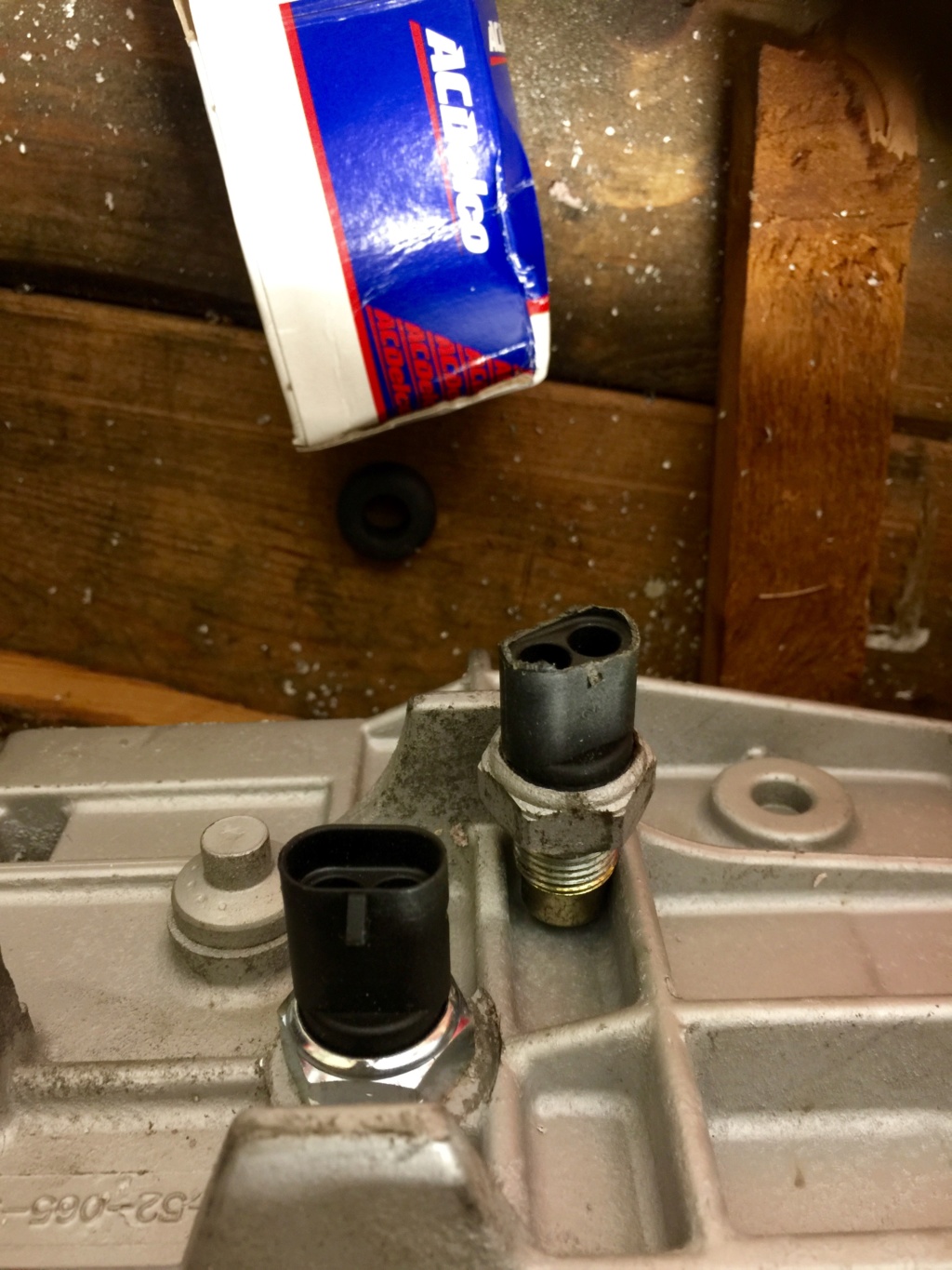
Since I was fiddling about with the gearbox anyway I replaced the backup light switch. The problem with the old one was that the switch housing was broken, not allowing the weatherpack connector to mate properly with it. Rather than fuss about with glue and whatnot I opted to replace the switch with an original AC Delco part.

To assemble the clutch onto the flywheel, you need special bolts. These are the ones apparently. I'll do that job later this week I hope.

I cleaned up and reattached the oil filter adapter housing. I'd lost one of the bolts so had to make another trip to Fastenal. 11 ft-lbs + 50 degrees later and the adapter is reattached. You'll also notice that I replaced the stock oil pressure sender unit with the new Speedhut item. The brass thread adapter was required.

Motor mounts back on. While I was doing the job I noticed that one of the knock sensors has rusted out. Ordered a replacement online.
Also over the weekend I went back and installed the bulkhead/firewall stearing bearing. Photos of that to follow.
The first order of business was to clean up and powder coat the motor mounts and the transmission tail mount. They cleaned up pretty well.
Here's the finished tail mount with the rubber bushings. I trimmed one of the studs short so it will fit inside the tail mount with clearance for the transmission bolt.
Tail mount and bushings attached to the transmission...
... but only after I stripped the thread out of one of the mounting holds.
Since I was fiddling about with the gearbox anyway I replaced the backup light switch. The problem with the old one was that the switch housing was broken, not allowing the weatherpack connector to mate properly with it. Rather than fuss about with glue and whatnot I opted to replace the switch with an original AC Delco part.
To assemble the clutch onto the flywheel, you need special bolts. These are the ones apparently. I'll do that job later this week I hope.
I cleaned up and reattached the oil filter adapter housing. I'd lost one of the bolts so had to make another trip to Fastenal. 11 ft-lbs + 50 degrees later and the adapter is reattached. You'll also notice that I replaced the stock oil pressure sender unit with the new Speedhut item. The brass thread adapter was required.
Motor mounts back on. While I was doing the job I noticed that one of the knock sensors has rusted out. Ordered a replacement online.
Also over the weekend I went back and installed the bulkhead/firewall stearing bearing. Photos of that to follow.
comled- Posts : 179
Join date : 2015-10-07
Location : New Hope, PA -
Re: Classic R #27 Build - Final Assembly
![]() by comled Wed Aug 15, 2018 11:38 pm
by comled Wed Aug 15, 2018 11:38 pm
Took the engine off the stand tonight so I could bolt on the flywheel and assemble the clutch pressure and friction plates and pilot bearing.

I couldn't work out how to attach the flywheel. A quick email to Scott confirmed that it only goes on one way and every hole gets a bolt. I had to fiddle with it for quite a while before it would line up but it did eventually.
[EDIT] These are the special GM single use flywheel bolts, part number 24505092. I had ordered them thinking they weren't in the kit but when I was unpacking after moving house I found them in the clutch kit box.
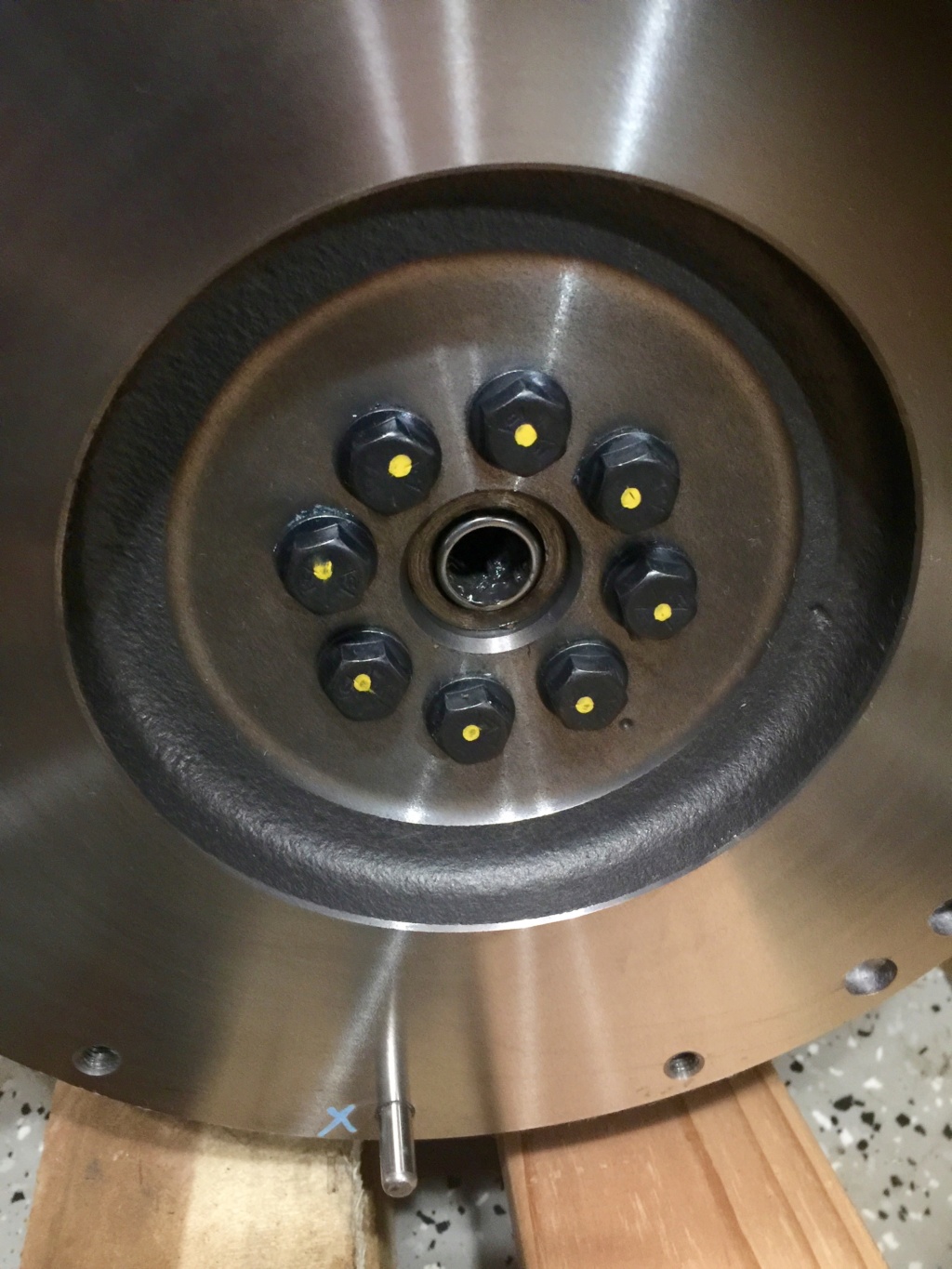
Bolted on and torqued to 11 lb ft + 50 degrees. You can feel the bolts stretch as you crank them down. In this shot you can see the pilot bearing installed with a small amount of grease. The yellow paint dot is my reminder that I have thread locked and torqued the bolt to its intended setting. It's easy to lose track otherwise of what's been done.
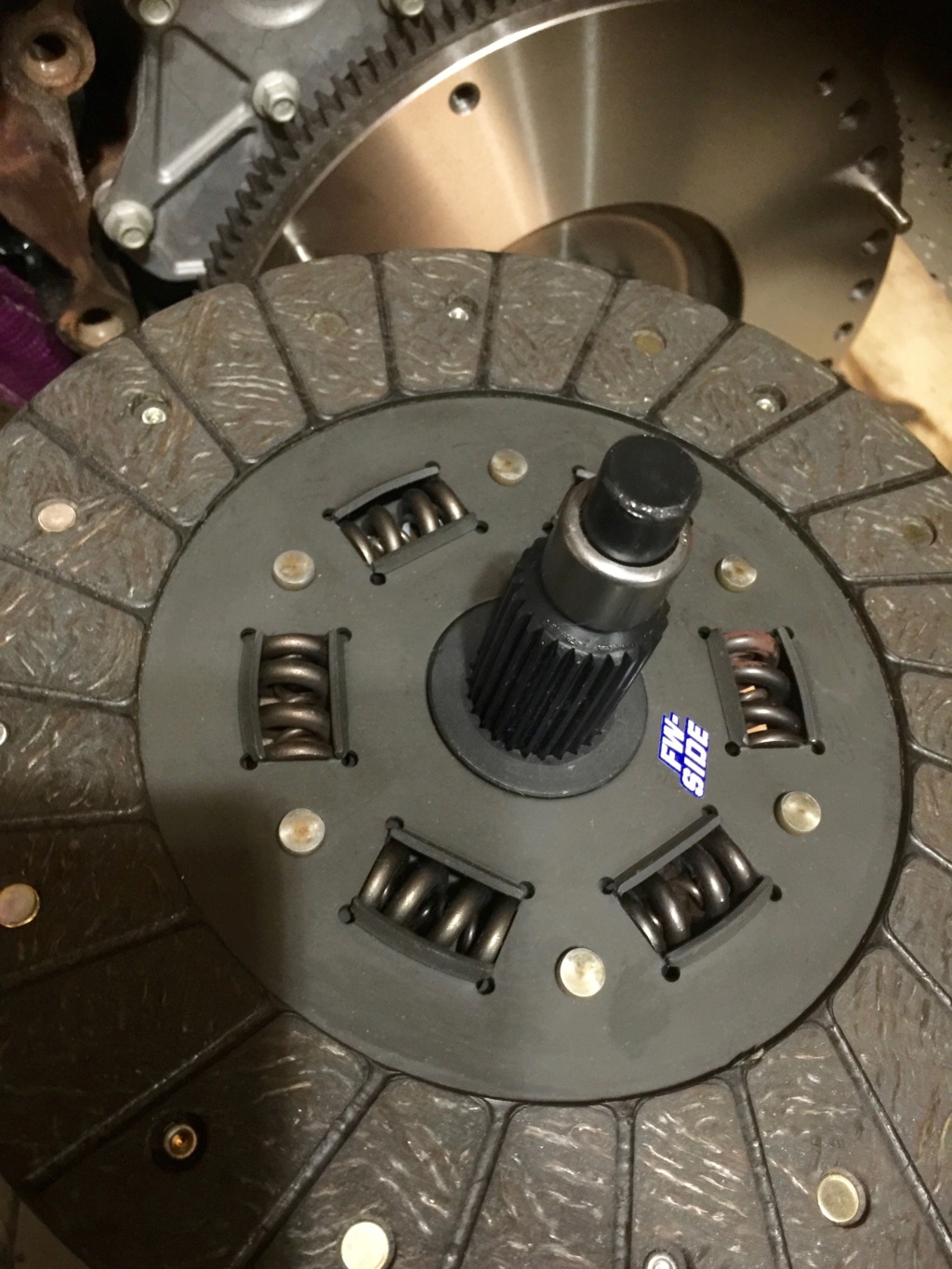
Slightly misleading sequence of photos here but here's the friction plate and centering tool (with the pilot bearing stuck on it). I wiped the surfaces of the friction plate down with lacquer thinner to degrease them, and did the same for the flywheel and pressure plate.
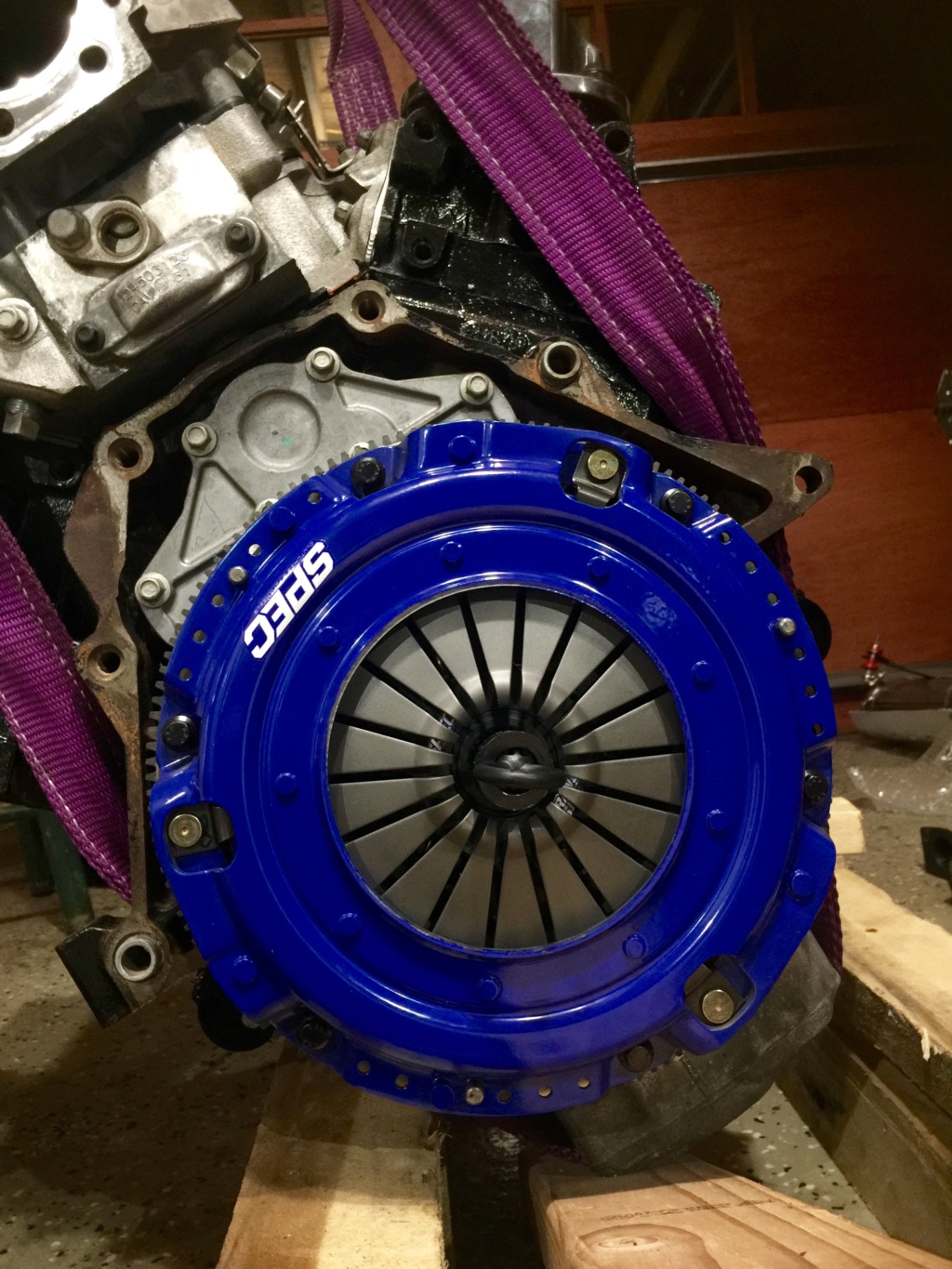
Assembled clutch and flywheel. Still need to torque the bolts down. The centering tool is a comfortable fit in the friction plate and pilot bearing. Next I'll bolt the transmission on and it will be ready to put back in the car.
I couldn't work out how to attach the flywheel. A quick email to Scott confirmed that it only goes on one way and every hole gets a bolt. I had to fiddle with it for quite a while before it would line up but it did eventually.
[EDIT] These are the special GM single use flywheel bolts, part number 24505092. I had ordered them thinking they weren't in the kit but when I was unpacking after moving house I found them in the clutch kit box.
Bolted on and torqued to 11 lb ft + 50 degrees. You can feel the bolts stretch as you crank them down. In this shot you can see the pilot bearing installed with a small amount of grease. The yellow paint dot is my reminder that I have thread locked and torqued the bolt to its intended setting. It's easy to lose track otherwise of what's been done.
Slightly misleading sequence of photos here but here's the friction plate and centering tool (with the pilot bearing stuck on it). I wiped the surfaces of the friction plate down with lacquer thinner to degrease them, and did the same for the flywheel and pressure plate.
Assembled clutch and flywheel. Still need to torque the bolts down. The centering tool is a comfortable fit in the friction plate and pilot bearing. Next I'll bolt the transmission on and it will be ready to put back in the car.
comled- Posts : 179
Join date : 2015-10-07
Location : New Hope, PA -
Re: Classic R #27 Build - Final Assembly
![]() by comled Sun Aug 19, 2018 8:40 am
by comled Sun Aug 19, 2018 8:40 am

I scoured the web for torque settings for the pressure plate bolts. With no definitive results in hand I went back to the packaging for the bolts only to find this handy table of torque values on a slip of paper behind the screws.

Engine and transmission reunited. I used the winch and the leveler to position the engine, and a motorcycle jack to raise and lower the transmission to stick the input shaft into the clutch and pilot bearing, confirming engagement by sticking the transmission into 4th, rotating the crankshaft and feeling for motion on the output shaft.

Friday night I transferred the engine and transmission to the shop crane reading for installation Saturday morning. The weather threatened to be stormy so I originally planned to do the job indoors but it turned out fine so I moved everything outside for ease of access (and unlimited headroom).

The other job I did Friday night was to powdercoat the driver's side outer transmission tunnel panel. It just fits in the Eastwood powdercoating oven. I installed it before dropping the engine in because once the transmission is in there's not much clearance for installing the screws that hold the panel on.

I lined the engine bay and transmission tunnel with moving blankets to avoid dinging the finish on the frame and the panels.
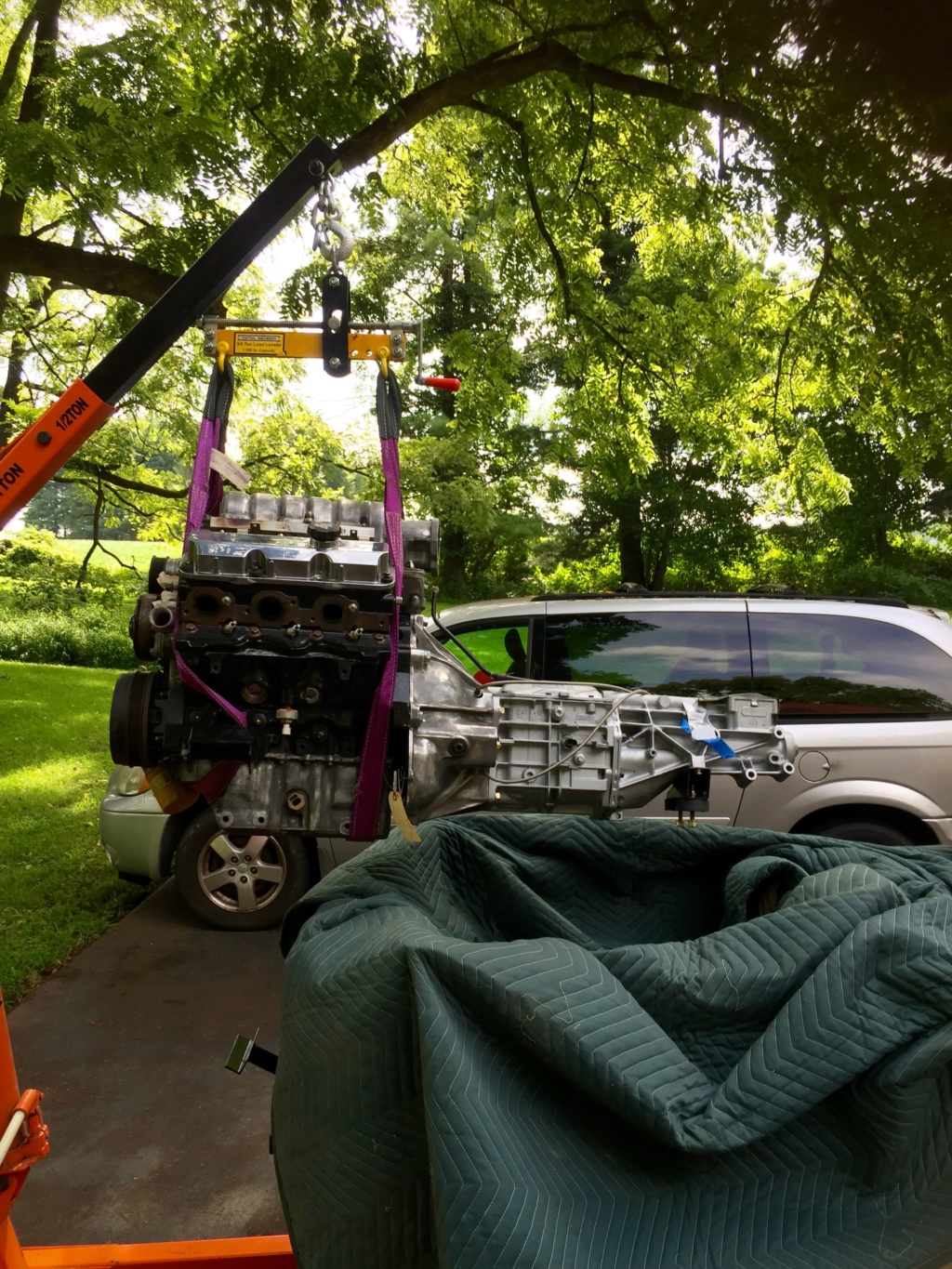
Game on. Lift the engine up so it's higher than the frame...

... tilt forward and nose dive it in. Then it's a matter of lower a bit, move forward a bit, level a bit until it's in the right spot.

Everything's bolted in loosely and lined up. The tail mount gave no trouble at all. In fact it almost dropped in on its own. No marks on the frame either.

One thing I did not do during the dry build was to install the prop shaft. I didn't realize until I came to do it that there are two sets of holes around the end that mates with the differential. Only one set will line up properly.

No surprises on the gearbox end. I wiped the splines and the seal surface with a little ATF before installing.

Back in and job done. All in all it was a couple of hours working alone. I'm sure it could be done faster but I was in no hurry.
comled- Posts : 179
Join date : 2015-10-07
Location : New Hope, PA -
Re: Classic R #27 Build - Final Assembly
![]() by comled Sun Aug 19, 2018 11:13 pm
by comled Sun Aug 19, 2018 11:13 pm

Replaced the drivers side knock sensor today.

While I was there I bolted in the starter motor. When the engine was out I'd taken the opportunity to measure the distance between the ring gear teeth and the shaft on the starter. It's supposed to be 1/8" and it was pretty close to that. If shims are needed I can add later.

This is the gearbox lubricant that I settled on. Just over 2 quarts were enough to fill the gearbox case.

The fill plug is located on the passenger side behind where the tunnel panel would be. It should be tightened to 22 lb ft. It's the same size as a 3/8" square drive hole so no special tool is needed.
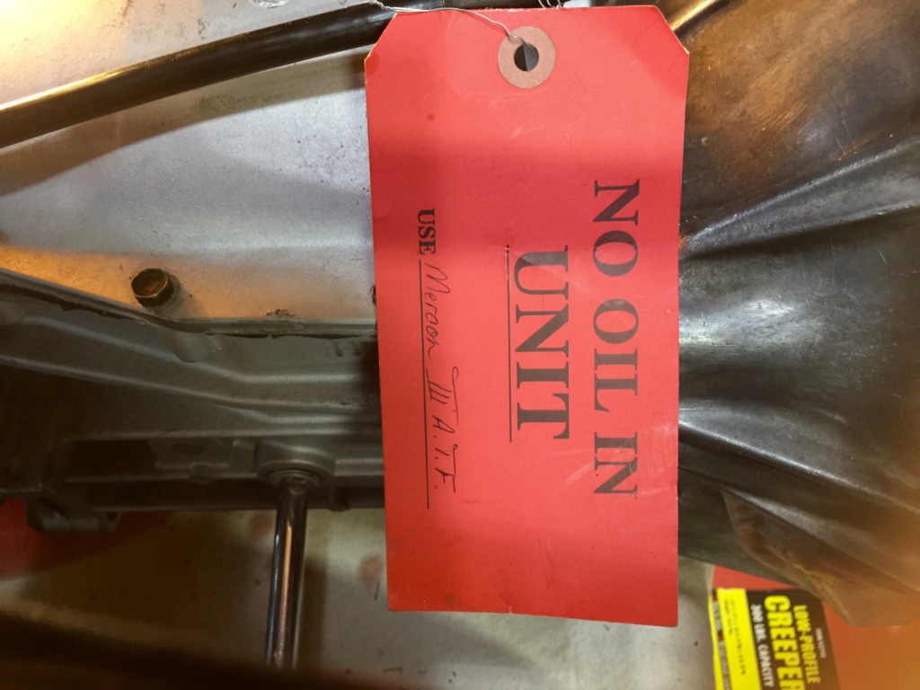
I removed the label after filling the gearbox. The label rather confusingly references Mercon III which is probably an erroneous reference to Mercon or Dexron III.
comled- Posts : 179
Join date : 2015-10-07
Location : New Hope, PA -
Re: Classic R #27 Build - Final Assembly
![]() by comled Wed Aug 29, 2018 8:52 am
by comled Wed Aug 29, 2018 8:52 am

My 2AWG battery cable arrived from CE Auto Electronics. It's very flexible and easy to work with.

Also in the mail was this braided ground strap. It's an AC Delco part, EGS18. I roughed in the ground strap and battery ground. It all has to be tidied up and routed so nothing hangs down.

I used the same 2AWG cable for the positive battery connection. Still have to make decisions about how to route all this wiring.

This hydraulic lug crimper handles a bunch of lug sizes and works like a charm.

The powder coat oven got a workout last night. I coated the front brake caliper brackets, all of the alternator mounting parts and this brace that fits under the bulkhead panel and supports the throttle pedal linkage. I think this is the last part that has to go under the bulkhead so I can start thinking about fitting that in due course.

I'm also finalizing placement of the fuse/relay boxes. I completed the schematic work, load calculations and fuse/relay assignments at the weekend so I know how many boxes I need and which circuits will be serviced by each box. I want to mount these on a panel that drops down exposing the front of each box into the passenger footwell. That way I can have the rear of each fuse box accessible for assembly, and access to the front for maintenance after the scuttle has been installed.

Finally I began reinstallation of the footwell panels. This is the passenger side panel, a bit hard to see in the low light but I like how the black powder coated panels worked out.
comled- Posts : 179
Join date : 2015-10-07
Location : New Hope, PA -
Re: Classic R #27 Build - Final Assembly
![]() by comled Tue Sep 11, 2018 7:40 am
by comled Tue Sep 11, 2018 7:40 am
This thread was getting a bit long so I added a part 2. Click here to resume reading.
comled- Posts : 179
Join date : 2015-10-07
Location : New Hope, PA -
» Classic R #27 Build - Final Assembly - Part 2
» Classic R #27 Build - Final Assembly - Part 3
» Classic R #27 Build - Final Assembly - Part 4
» Classic R #27 Build - Final Assembly - Part 5
» Classic R #27 Build - Final Assembly - Part 6
» Classic R #27 Build - Final Assembly - Part 3
» Classic R #27 Build - Final Assembly - Part 4
» Classic R #27 Build - Final Assembly - Part 5
» Classic R #27 Build - Final Assembly - Part 6
Page 1 of 1
Permissions in this forum:
You cannot reply to topics in this forum|
|
|