Classic R #27 Build - Cooling System
Page 1 of 1
 Classic R #27 Build - Cooling System
It's been a busy couple of weeks on the car front. I started roughing out ideas for the cooling system a week or so back. To backtrack for a moment, I was re-reading the PA regs for street cars and one thing I had not planned on was the requirement for a demister system. My interpretation of what the regs say is that if demisters were fitted to the predicate car (which in case would be a 1962 Lotus Seven, according to Stalker Cars), then the replica should have them too. However, having read many accounts of PA kit car owners' experiences with the inspection and registration process, it seems that demisters are a matter of necessity. It seems odd given that this is an open car, but I've no wish to get into a quarrel with the inspector - and it's no hardship to have a heater available for those chilly fall morning drives. So I decided to include them in the build, and that necessitated a rethink on the cooling system.
I considered two options: building a small electric air heater based on a 200W ceramic heating element and using the blower fan motor from some sort of donor car; or plumbing a heater matrix into the cooling system. I didn't really want to go the heater matrix approach because I had already blocked off the water port in the block that would have been the ideal takeoff point for the inlet side of the heater, and I'd also blocked off the port on the water pump that would have been the return point. But there are other options for plumbing and I eventually concluded that I would not go the electric route because I've only got a small alternator and battery to power the heater/fan motor combination. So water heat it will be.

I cast around for a small unit and found this Maradyne part. This is the front view. It's a cube a little over 7" on each side, it has 5/8" water inlet and outlet port on the rear face, three vents and two ports for hooking up air ducts to drive the demister vents. The fan motor and core are integrated into one small box, and it comes with a 3 speed heater fan control switch (which is resistive by the way: the instructions state that the switch should be mounted at least 3" away from any other parts).

Here's the back side of the unit showing the ports and the mounting studs. The kit comes with a drilling template so it should be relatively straightforward. I am going to mount this on the firewall either by bolting it on directly or by making up a bracket to compensate for the angle of the firewall. I have room under the scuttle right in the middle of the car and that spot will allow all three passenger vents to be accessible from the cockpit, but the unit will be far enough back that I can run the vent hoses fairly unobtrusively.
So that's all good. In order to plumb this in I am going to use two tees, one in the upper radiator hose before the thermostat, and one in the lower radiator hose, to provide 5/8" hose takeoffs. That means ditching the thermostat inside the 3800's water neck and putting an inline thermostat housing in the upper hose instead, after the heater tee. I ordered the tees and a Mezniere 1 1/4" inline thermostat housing and will post pictures as that part of the cooling system progresses.
I also ordered the radiator identified on the shopping list. The 1987 Hyundai Excel 1.5 radiator is quite small but even so it still has to be mounted at an angle to fit.

Here's the happy sight that greeted me when I opened the box. Obviously it will have to go back to the supplier. However since I had it in hand I lined it up on the frame so I could understand all the clearances, mounts and ports.

This is what the radiator actually looks like. It's a CU349 model with a copper core, a transmission cooler, filler neck, inlet and outlet ports and a drain port - pretty typical stuff.

To accomodate the radiator's overall height it has to be tilted backward. This allows the hood nose to fit over it.

I'm not wild about the clearances to the suspension, nor am I wild about the angle of that filler neck. In fact this filler isn't really needed: a simple port in the top of the radiator at the highest point in the system would do a better job.
I think we can do a little better. The Mark Scott Prototype Developments radiator is custom-made for the Stalker, but I don't think it's available any more. I tried to get onto the Prototype Developments web site but the domain seems to have expired so that doesn't seem a viable route.
My racing friend Tony has a number of racecars with custom radiators installed in them. I've seen them up close and they are works of art. So on Friday I took a half day off work and he and I headed over to Art's Radiators in Flemington, NJ to see about a custom radiator for the Seven.


Before we left, I made a bunch of measurements off the Hyundai radiator, sketched it and then noted some of things I wanted to change. Art suggested that we come up with a design that moves top and bottom tanks to the sides, move the ports around to improve coolant flow and to have them better align to the available space in the car. We left it that he would assemble the outer shell first and have me trial fit that in the car to confirm alignment. It will be an aluminum radiator, obviously. The filler neck will go and be replaced with a screw in port at the top of the radiator. The radiator top surface will be angled to match the installation angle in the car. The curved lower hose port will go and be replaced by a 1 3/4" stub. The top hose port moves from its current central location to a point on the drivers side. In terms of the cooling fan, we will switch from a single 14" pusher to an array of smaller puller fans sized to suit the core size. To maximize airflow over the angled core, a removable aluminum shroud will be scribed to the outline of the nose. I don't have technical specs yet on the tube size, number of rows or core area so watch this space as Art's design progresses.
I have one more job to add to Art's list and that is to cut and reweld the L26's water neck so that it exits the head at 90 degrees. In most V6 Stalkers, the builder installs a combination of hose couplers that compensate for the odd water neck angle. In the Mark Scott car, the design takes advantage of that space to install a water tank, but in the later models like the Classic R that have a brake booster, that's not feasible. The water neck coupler usually runs into an aluminum pipe that runs above the headers and feeds the radiator upper hose through another arrangement of hoses. I want to square that angle off and see about running my plumbing underneath the header instead of above it. That will make for a cleaner engine bay appearance I think and it's one less thing to burn your hand on when everything's hot.
Speaking of headers, I rounded off the week by getting a quote from Jet-Hot for coating the headers - $405. Welcome to the money pit folks.
-Dave
I considered two options: building a small electric air heater based on a 200W ceramic heating element and using the blower fan motor from some sort of donor car; or plumbing a heater matrix into the cooling system. I didn't really want to go the heater matrix approach because I had already blocked off the water port in the block that would have been the ideal takeoff point for the inlet side of the heater, and I'd also blocked off the port on the water pump that would have been the return point. But there are other options for plumbing and I eventually concluded that I would not go the electric route because I've only got a small alternator and battery to power the heater/fan motor combination. So water heat it will be.

I cast around for a small unit and found this Maradyne part. This is the front view. It's a cube a little over 7" on each side, it has 5/8" water inlet and outlet port on the rear face, three vents and two ports for hooking up air ducts to drive the demister vents. The fan motor and core are integrated into one small box, and it comes with a 3 speed heater fan control switch (which is resistive by the way: the instructions state that the switch should be mounted at least 3" away from any other parts).

Here's the back side of the unit showing the ports and the mounting studs. The kit comes with a drilling template so it should be relatively straightforward. I am going to mount this on the firewall either by bolting it on directly or by making up a bracket to compensate for the angle of the firewall. I have room under the scuttle right in the middle of the car and that spot will allow all three passenger vents to be accessible from the cockpit, but the unit will be far enough back that I can run the vent hoses fairly unobtrusively.
So that's all good. In order to plumb this in I am going to use two tees, one in the upper radiator hose before the thermostat, and one in the lower radiator hose, to provide 5/8" hose takeoffs. That means ditching the thermostat inside the 3800's water neck and putting an inline thermostat housing in the upper hose instead, after the heater tee. I ordered the tees and a Mezniere 1 1/4" inline thermostat housing and will post pictures as that part of the cooling system progresses.
I also ordered the radiator identified on the shopping list. The 1987 Hyundai Excel 1.5 radiator is quite small but even so it still has to be mounted at an angle to fit.

Here's the happy sight that greeted me when I opened the box. Obviously it will have to go back to the supplier. However since I had it in hand I lined it up on the frame so I could understand all the clearances, mounts and ports.

This is what the radiator actually looks like. It's a CU349 model with a copper core, a transmission cooler, filler neck, inlet and outlet ports and a drain port - pretty typical stuff.

To accomodate the radiator's overall height it has to be tilted backward. This allows the hood nose to fit over it.

I'm not wild about the clearances to the suspension, nor am I wild about the angle of that filler neck. In fact this filler isn't really needed: a simple port in the top of the radiator at the highest point in the system would do a better job.
I think we can do a little better. The Mark Scott Prototype Developments radiator is custom-made for the Stalker, but I don't think it's available any more. I tried to get onto the Prototype Developments web site but the domain seems to have expired so that doesn't seem a viable route.
My racing friend Tony has a number of racecars with custom radiators installed in them. I've seen them up close and they are works of art. So on Friday I took a half day off work and he and I headed over to Art's Radiators in Flemington, NJ to see about a custom radiator for the Seven.


Before we left, I made a bunch of measurements off the Hyundai radiator, sketched it and then noted some of things I wanted to change. Art suggested that we come up with a design that moves top and bottom tanks to the sides, move the ports around to improve coolant flow and to have them better align to the available space in the car. We left it that he would assemble the outer shell first and have me trial fit that in the car to confirm alignment. It will be an aluminum radiator, obviously. The filler neck will go and be replaced with a screw in port at the top of the radiator. The radiator top surface will be angled to match the installation angle in the car. The curved lower hose port will go and be replaced by a 1 3/4" stub. The top hose port moves from its current central location to a point on the drivers side. In terms of the cooling fan, we will switch from a single 14" pusher to an array of smaller puller fans sized to suit the core size. To maximize airflow over the angled core, a removable aluminum shroud will be scribed to the outline of the nose. I don't have technical specs yet on the tube size, number of rows or core area so watch this space as Art's design progresses.
I have one more job to add to Art's list and that is to cut and reweld the L26's water neck so that it exits the head at 90 degrees. In most V6 Stalkers, the builder installs a combination of hose couplers that compensate for the odd water neck angle. In the Mark Scott car, the design takes advantage of that space to install a water tank, but in the later models like the Classic R that have a brake booster, that's not feasible. The water neck coupler usually runs into an aluminum pipe that runs above the headers and feeds the radiator upper hose through another arrangement of hoses. I want to square that angle off and see about running my plumbing underneath the header instead of above it. That will make for a cleaner engine bay appearance I think and it's one less thing to burn your hand on when everything's hot.
Speaking of headers, I rounded off the week by getting a quote from Jet-Hot for coating the headers - $405. Welcome to the money pit folks.
-Dave
 Re: Classic R #27 Build - Cooling System
It's been several weeks since I had a decent full-on weekend working on the car but I have been nibbling away getting small jobs done.
Update on the heater - it's installed.

I already knew I wanted to fit the heater unit in the center of the car inside the scuttle area. The Maradyne unit comes with a drilling template. I figured the height to mount it above the tunnel cover by shimming it with strips of wood, then taped the drilling template to the firewall before removing the firewall and drilling out with a hole drill. A note of caution: my heater came with two drilling templates. One of the templates is just plain wrong - it's undersized. The one inside the manual is correct. It just has to be photocopied 1:1, cut out and stick on.

I didn't want to mount the heater on the tunnel cover, and the firewall is too flimsy to support its weight unaided so I fabricated some items to facilitate installation. First I made two brackets by cutting, bending and welding 3/4" x 1/8" steel bar to take the weight of the heater. These steel brackets do the job fine and will be powder coated later. One end of each bracket mounts to the frame, the other to the lower bar of the dash. The lowest part in the image is an aluminum trim strip I bent from a piece of 1" x 1/8" aluminum bar - it's visible from within the cockpit and tidies up the front view of the heater.

I found these 3/8-16 threaded hex spacers at the hardware store and also selected locknuts to match. The spacers hold the heater clear of the firewall and brings it just far enough forward that, from inside the cockpit, you can reach the heater vent flaps to open and close them manually.

Brackets held in place with clecos for now.

The heater drops right into place in the cradle. I will run a screw in each corner through the bracket into the heater box to hold it in place. I'll probably dress up the firewall where the heater hoses pass through: I may make up pass-throughs out of aluminum or something to give the installation a finished appearance.
-Dave
Update on the heater - it's installed.

I already knew I wanted to fit the heater unit in the center of the car inside the scuttle area. The Maradyne unit comes with a drilling template. I figured the height to mount it above the tunnel cover by shimming it with strips of wood, then taped the drilling template to the firewall before removing the firewall and drilling out with a hole drill. A note of caution: my heater came with two drilling templates. One of the templates is just plain wrong - it's undersized. The one inside the manual is correct. It just has to be photocopied 1:1, cut out and stick on.

I didn't want to mount the heater on the tunnel cover, and the firewall is too flimsy to support its weight unaided so I fabricated some items to facilitate installation. First I made two brackets by cutting, bending and welding 3/4" x 1/8" steel bar to take the weight of the heater. These steel brackets do the job fine and will be powder coated later. One end of each bracket mounts to the frame, the other to the lower bar of the dash. The lowest part in the image is an aluminum trim strip I bent from a piece of 1" x 1/8" aluminum bar - it's visible from within the cockpit and tidies up the front view of the heater.

I found these 3/8-16 threaded hex spacers at the hardware store and also selected locknuts to match. The spacers hold the heater clear of the firewall and brings it just far enough forward that, from inside the cockpit, you can reach the heater vent flaps to open and close them manually.

Brackets held in place with clecos for now.

The heater drops right into place in the cradle. I will run a screw in each corner through the bracket into the heater box to hold it in place. I'll probably dress up the firewall where the heater hoses pass through: I may make up pass-throughs out of aluminum or something to give the installation a finished appearance.
-Dave
 Re: Classic R #27 Build - Cooling System
My radiator build is under way and I picked up the initial version of it this week to in order to check the fit.

Here's what Art came up with. The tanks have been moved to the sides rather than top and bottom (underneath the blue masking tape which I used to hold the radiator in place while I put the hood on). The filler is a small bung on the top tank that takes up almost no room. A corresponding drain plug will go in the opposite corner on the bottom, as will the lower hose port. Owing to the arrangement of the tanks and core, both the upper and lower coolant hose ports will be on the same side of the car.
It looks huge - but in fact it fills the opening in the hood really well. The only problem at this stage is that the top corners interfere with the hood but they can easily be removed.

Here's the view from the front with the hood in place. There's some finessing to do to eliminate airflow between the side of the hood and the radiator, but it's no big deal.
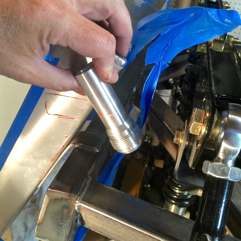
I'm going to use an AN fitting on the upper port (which will be on the passenger side by the way). Here I am figuring the angle to install the port at. It will have to be angled because the suspension is pretty close to the port and may not leave enough room for an elbow. By angling the port at about 30 degrees to the radiator I can avoid the need for the elbow altogether.
I marked everything up and returned it today so hopefully this will be well along by the end of next week.

Update: I wanted to add this picture which shows how the radiator is affecting hood fit. If you look toward the front of the car near the headlamp mounting bracket you can see the gap between the bottom of the hood and the frame where the top corners of the radiator are in contact with the inside of the hood.
-Dave

Here's what Art came up with. The tanks have been moved to the sides rather than top and bottom (underneath the blue masking tape which I used to hold the radiator in place while I put the hood on). The filler is a small bung on the top tank that takes up almost no room. A corresponding drain plug will go in the opposite corner on the bottom, as will the lower hose port. Owing to the arrangement of the tanks and core, both the upper and lower coolant hose ports will be on the same side of the car.
It looks huge - but in fact it fills the opening in the hood really well. The only problem at this stage is that the top corners interfere with the hood but they can easily be removed.

Here's the view from the front with the hood in place. There's some finessing to do to eliminate airflow between the side of the hood and the radiator, but it's no big deal.

I'm going to use an AN fitting on the upper port (which will be on the passenger side by the way). Here I am figuring the angle to install the port at. It will have to be angled because the suspension is pretty close to the port and may not leave enough room for an elbow. By angling the port at about 30 degrees to the radiator I can avoid the need for the elbow altogether.
I marked everything up and returned it today so hopefully this will be well along by the end of next week.

Update: I wanted to add this picture which shows how the radiator is affecting hood fit. If you look toward the front of the car near the headlamp mounting bracket you can see the gap between the bottom of the hood and the frame where the top corners of the radiator are in contact with the inside of the hood.
-Dave
 Re: Classic R #27 Build - Cooling System
A couple of weeks back I had removed the plenum and lower intake manifold because I wanted to experiment with putting an intake from a RWD Camaro on the car. That intake is compatible with the L26 block and heads and I found a way to shorten it so that it would fit under the hood. Ultimately I abandoned that line of research as it would have resulted in performance issues - and probably a change to the ECM setups. However... since I had the lower intake manifold off, and there's a port in the LIM that I had previously blocked off with a core plug, I decided to open that port, expand it out and install a flare fitting for a heater takeoff point. I also opened up the port on the water pump.

3/4" NPT tap, -10 to 3/4" male flare fitting, aluminum fitting wrench.

The 59/64" drill bit I ordered for the job arrived as a 3/4" drill bit so I resorted to reaming out the LIM port to the required size using these adjustable reamers from an HF kit I had on hand. For what it's worth, I ended up using sizes F and G, taking multiple small cuts and measuring until I hit 59/64".
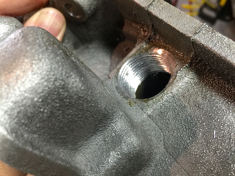
Threaded port ready to accept the flare fitting.

Flare fitting installed.

The hole in the water pump is exactly the right size for the 3/4 NPT threaded flare fitting. I used an 18mm socket because I didn't have a big enough tap handle.

Threaded water pump port for the heater return line...
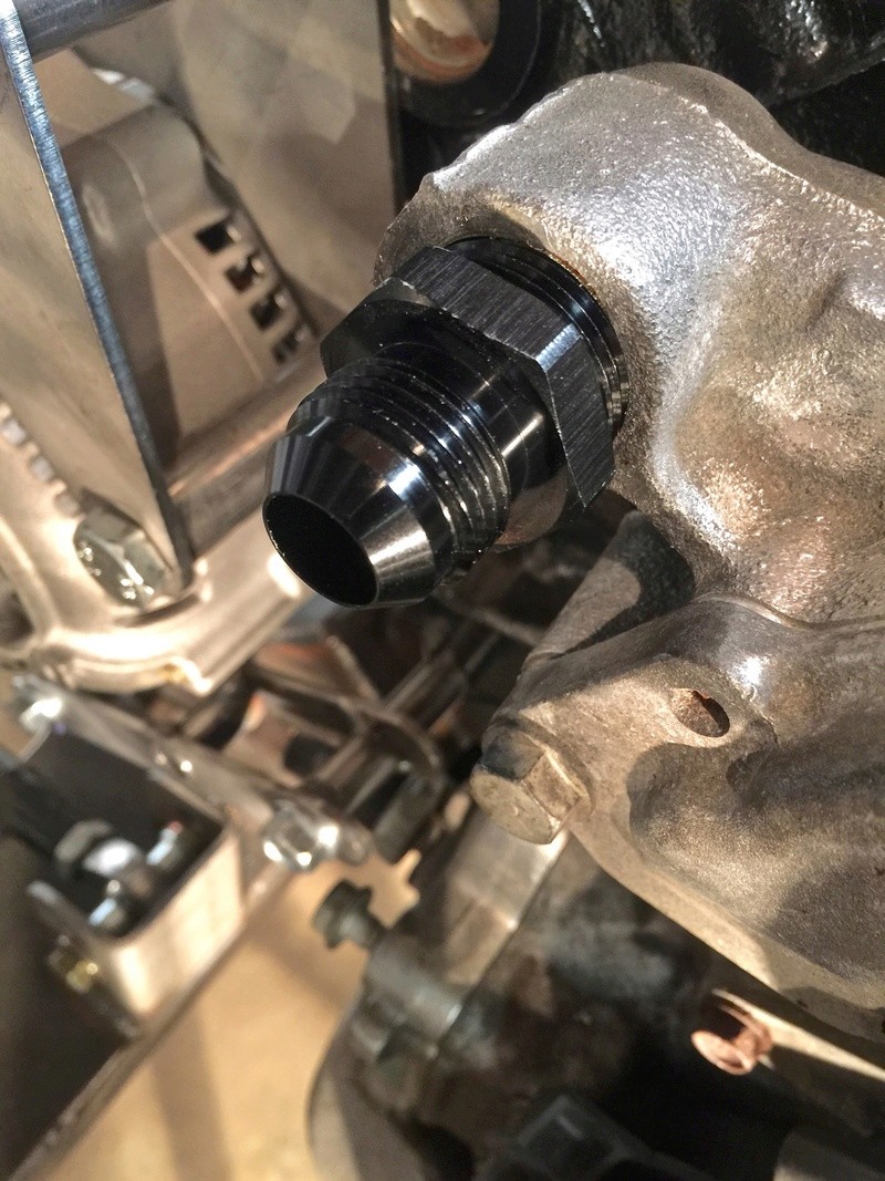
... and the fitting installed.
Today I ordered -10 hose and swivel fittings to run from these two ports to the heater; they should be here shortly. I'll have a bit of hose left over to do the lines for the remote oil filter housing. In the meantime I need to reassemble the LIM and plenum onto the engine. I took the opportunity to clean things up a bit while I had the LIM off.
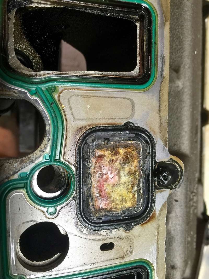
Mmmm... Dex-Cool goodness. Fortunately this was just build-up on a closed surface, not a coolant route through the LIM.
-Dave

3/4" NPT tap, -10 to 3/4" male flare fitting, aluminum fitting wrench.

The 59/64" drill bit I ordered for the job arrived as a 3/4" drill bit so I resorted to reaming out the LIM port to the required size using these adjustable reamers from an HF kit I had on hand. For what it's worth, I ended up using sizes F and G, taking multiple small cuts and measuring until I hit 59/64".

Threaded port ready to accept the flare fitting.

Flare fitting installed.

The hole in the water pump is exactly the right size for the 3/4 NPT threaded flare fitting. I used an 18mm socket because I didn't have a big enough tap handle.

Threaded water pump port for the heater return line...

... and the fitting installed.
Today I ordered -10 hose and swivel fittings to run from these two ports to the heater; they should be here shortly. I'll have a bit of hose left over to do the lines for the remote oil filter housing. In the meantime I need to reassemble the LIM and plenum onto the engine. I took the opportunity to clean things up a bit while I had the LIM off.

Mmmm... Dex-Cool goodness. Fortunately this was just build-up on a closed surface, not a coolant route through the LIM.
-Dave
 Re: Classic R #27 Build - Cooling System
Minor progress this weekend. I cleaned up the LIM and the mating surfaces on the block, ordered new aluminum gaskets and reinstalled the LIM.
Before reinstalling I cleaned the LIM thoroughly, especially the gasket mating surfaces. I picked up a 5/16-18 tap and die from the hardware store and chased all the threads in the block with the tap, and cleaned the corresponding screw threads with the die. It worked like a charm: all the bolts went in by hand to finger tightness. I used blue thread locker and torqued to 11 lb ft using the standard bolt sequence. Absent a manual for the engine I used the Pontiac Bonneville writeup at http://www.pontiacbonnevilleclub.com/forum/engine/topic3591.html.

Here's the LIM dropped into place after installing the end seals with a little black RTV to help.

LIM installed and all bolts threadlockered (is that the right verb?) and torqued to spec.

Part number of the aluminum gasket set I used - from zzperformance.com.

Had to check clearance between the -10 hose fittings and the ports I installed - all looks good. Hose arrives Wednesday hopefully so I can get on with the plumbing. The ports are lower left and mid-right hand side.

Also installed the Speedhut temperature sender unit after removing the stock temperature sender, but thinking about it I may need to take it out again and find a way to mount both sensors because I don't know whether the characteristic curves are the same for each sensor, and an ECT signal is required for the PCM. Researching that now to see if they match or whether both sensors are needed.
-Dave
Before reinstalling I cleaned the LIM thoroughly, especially the gasket mating surfaces. I picked up a 5/16-18 tap and die from the hardware store and chased all the threads in the block with the tap, and cleaned the corresponding screw threads with the die. It worked like a charm: all the bolts went in by hand to finger tightness. I used blue thread locker and torqued to 11 lb ft using the standard bolt sequence. Absent a manual for the engine I used the Pontiac Bonneville writeup at http://www.pontiacbonnevilleclub.com/forum/engine/topic3591.html.

Here's the LIM dropped into place after installing the end seals with a little black RTV to help.

LIM installed and all bolts threadlockered (is that the right verb?) and torqued to spec.

Part number of the aluminum gasket set I used - from zzperformance.com.

Had to check clearance between the -10 hose fittings and the ports I installed - all looks good. Hose arrives Wednesday hopefully so I can get on with the plumbing. The ports are lower left and mid-right hand side.

Also installed the Speedhut temperature sender unit after removing the stock temperature sender, but thinking about it I may need to take it out again and find a way to mount both sensors because I don't know whether the characteristic curves are the same for each sensor, and an ECT signal is required for the PCM. Researching that now to see if they match or whether both sensors are needed.
-Dave
 Re: Classic R #27 Build - Cooling System

Working from the basis that both temperature senders are required, I removed the Speedhut temperature sensor, added a brass street tee (and a 3/8-3/8 coupler to provide a bit of clearance from the LIM and the transmission bellhousing) and installed both temperature sensors. The street tee is an Amazon item (Anderson Metals Brass Pipe Fitting, Barstock Street Tee, 3/8" Female Pipe x 3/8" Male Pipe x 3/8" Female Pipe, part number ANEIZ0390. The threaded coupler is a Eaton Weatherhead 3200X6 Brass CA360 Fitting, Adapter, 3/8" NPT Female x 3/8" NPT Male, part number 3200X6.
Hoping to get a visit this week from Art's Radiators so we can finish up the radiator build.

Sometimes you get stuck on a detail and this was a case in point. I wanted to make a firewall/bulkhead passthrough fitting for the two heater hoses. I ordered -10 bulkhead nuts (sourced economically from eBay) and spent most of yesterday machining these two small aluminum parts just so the heater hose would go through the firewall cleanly. The outer diameter is 1 1/16", inner diameter is 0.9" to match the outer diameter of the -10 Russell push loc hose I am using.

Assembled firewall fittings ready to install.

Installed and ready to accept heater hose at the appropriate time. Hope it was worth the effort...
-Dave
 Re: Classic R #27 Build - Cooling System

Finishing up reassembly of the upper intake manifold/plenum, I fitted a new gasket ready to bolt the plenum down. I wanted to include this picture from inside the L26 plenum which shows the clear plastic tube that feeds into the PCV area. The alignment of the tube may not be readily apparent at first; one end has to stick up into the PCV recess.
I chased the threads on the bolts and reassembled with blue loctite, torquing to 89 lb in using the correct sequence.
-Dave
 Re: Classic R #27 Build - Cooling System
Worked a bit more on the plumbing for the heater. I made two heater hose-to-heater barb couplers that will allow a -10 hose end to connect to the heater core through the firewall.
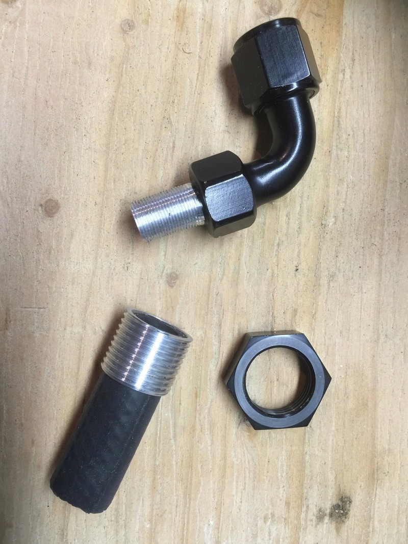
Raw materials - a 2 1/4" length of 5/8" heater hose; a -10 90 degree barbed swivel fitting with the barbs sanded off and threaded 5/8-24; and the threaded part of the firewall passthrough I'd made a few weeks ago. The black hose compresses slightly when it passes through the firewall passthrough and this allows the 5/8-24 threaded fitting to screw into it tightly. I'll brush on a little Permatex form-a-gasket when the time comes for final assembly.

The first coupler assembled through the firewall.

The second coupler assembled through the firewall. This one uses a slightly longer length of hose and the standard barb on the -10 fitting which results in the two fittings being spaced apart somewhat for clearance.
I've got some Russell 5/8" hose that I will use to plumb from the ports on the front of the engine to these new ports on the firewall but I'll most likely hold off running those lines until after the radiator and the headers are installed.
-Dave

Raw materials - a 2 1/4" length of 5/8" heater hose; a -10 90 degree barbed swivel fitting with the barbs sanded off and threaded 5/8-24; and the threaded part of the firewall passthrough I'd made a few weeks ago. The black hose compresses slightly when it passes through the firewall passthrough and this allows the 5/8-24 threaded fitting to screw into it tightly. I'll brush on a little Permatex form-a-gasket when the time comes for final assembly.

The first coupler assembled through the firewall.

The second coupler assembled through the firewall. This one uses a slightly longer length of hose and the standard barb on the -10 fitting which results in the two fittings being spaced apart somewhat for clearance.
I've got some Russell 5/8" hose that I will use to plumb from the ports on the front of the engine to these new ports on the firewall but I'll most likely hold off running those lines until after the radiator and the headers are installed.
-Dave
 Re: Classic R #27 Build - Cooling System
Exciting progress on the cooling system this week. Art, proprietor of Art's Radiators, made a house call to look at the car and to advise on the cooling system. He suggested an alternative layout for the ports on the radiator as well as the inline coolant filler, overflow bottle, temperature senders and the water neck. I wanted to share pictures of the parts he made for the car.

Here's the water neck he put together to replace the stock GM item. The hose barb on the GM part faces away from the radiator and would have required a bunch of elbows and custom plumbing to get it facing toward the front of the car. Also most builders run an aluminum pipe above the header to deal with the exhaust heat issue. In this custom water neck, the hose fitting exits the neck facing in the right direction. A braided -16 hose can run above the valve cover, well away from the header.

Art also provided a couple of ports in the water neck to accommodate the two temperature senders. He wasn't enthusiastic about my brass fittings screwed into the lower intake manifold temperature sender port because there would have been no water flow past the senders.

The radiator outline is basically unchanged from the prior iteration. There's a minor mismatch between the mounting brackets on the radiator and on the chassis: I can make those mountings on the chassis a little wider to accommodate the slightly wider radiator.

However, the upper port now has a 90 degree bend in it so it correctly clears the suspension.


Finally he made up this rather nice coolant filler neck which will be plumbed to be at more or less the highest point in the system. Plugs in the radiator and in the water neck will allow air to be purged from those parts of the system. He installed another fitting to feed the line for the overflow tank. That will also be a custom made part using 3" aluminum pipe.

Once I finish up work on the exhaust I'll get these parts fitted - hopefully this weekend...
-Dave

Here's the water neck he put together to replace the stock GM item. The hose barb on the GM part faces away from the radiator and would have required a bunch of elbows and custom plumbing to get it facing toward the front of the car. Also most builders run an aluminum pipe above the header to deal with the exhaust heat issue. In this custom water neck, the hose fitting exits the neck facing in the right direction. A braided -16 hose can run above the valve cover, well away from the header.

Art also provided a couple of ports in the water neck to accommodate the two temperature senders. He wasn't enthusiastic about my brass fittings screwed into the lower intake manifold temperature sender port because there would have been no water flow past the senders.

The radiator outline is basically unchanged from the prior iteration. There's a minor mismatch between the mounting brackets on the radiator and on the chassis: I can make those mountings on the chassis a little wider to accommodate the slightly wider radiator.

However, the upper port now has a 90 degree bend in it so it correctly clears the suspension.


Finally he made up this rather nice coolant filler neck which will be plumbed to be at more or less the highest point in the system. Plugs in the radiator and in the water neck will allow air to be purged from those parts of the system. He installed another fitting to feed the line for the overflow tank. That will also be a custom made part using 3" aluminum pipe.

Once I finish up work on the exhaust I'll get these parts fitted - hopefully this weekend...
-Dave
 Re: Classic R #27 Build - Cooling System
The new water neck/thermostat housing is installed. To accomplish this, I machined two studs from 3/8" dia mild steel. One end is tapped to suit the existing mounting holes in the lower intake manifold. From memory they're something like an M8-1.25 thread, tapped for about 3/4". The other end I tapped 5/16-24 for a length of 3/4", just because I like non-metric threads.

Cleaned the holes out with an M8-1.25 tap and installed the studs hand tight for now. Studs in place ready for the housing to be bolted down.

I picked up a couple of stainless 5/16-24 acorn nuts from McMaster to hold the thermostat housing down and I'll add spring washers to suit. I may need to shorten the studs a whisker to be sure of tightening the housing down enough to provide intimate contact with the thermostat seal.
-Dave

Cleaned the holes out with an M8-1.25 tap and installed the studs hand tight for now. Studs in place ready for the housing to be bolted down.

I picked up a couple of stainless 5/16-24 acorn nuts from McMaster to hold the thermostat housing down and I'll add spring washers to suit. I may need to shorten the studs a whisker to be sure of tightening the housing down enough to provide intimate contact with the thermostat seal.
-Dave
 Re: Classic R #27 Build - Cooling System
I've been preparing to attach the new radiator and cooling fan.

I started by grinding off the old radiator mounts. They didn't align to the brackets on the custom radiator because it's a bit wider than the stock Hyundai item.

Fabricated these new brackets by bending and welding pieces of 1" x 1/8" steel bar. They're positioned to match the radiator brackets and rather than mount them on the forward cross-member I used the vertical frame members instead, aligning everything with the radiator in place, then removing it and tack welding the brackets on.

Viewed from the side. There's about 3/8" clearance between the radiator and the bracket which will accommodate vibration-absorbing rubber mounts as the means of attachment.

This week I ordered most of the parts needed to finish plumbing in the heater. Just waiting for 27.1mm Oetiker clamps and then I hope to get this part of the build finished. I suspect it will be the most expensive heater installation in history. In the picture are 135 degree silicon elbows that attach to the heater takeoff points in the LIM and the water pump. I plan to route both hoses along the passenger side of the engine compartment where they will pick up the inlet and outlet ports for the heater at the firewall. It's more or less a straight shot across at this point and I will work out some means of securing the hoses so they don't flap about and interfere with the alternator belt.
-Dave

I started by grinding off the old radiator mounts. They didn't align to the brackets on the custom radiator because it's a bit wider than the stock Hyundai item.

Fabricated these new brackets by bending and welding pieces of 1" x 1/8" steel bar. They're positioned to match the radiator brackets and rather than mount them on the forward cross-member I used the vertical frame members instead, aligning everything with the radiator in place, then removing it and tack welding the brackets on.

Viewed from the side. There's about 3/8" clearance between the radiator and the bracket which will accommodate vibration-absorbing rubber mounts as the means of attachment.

This week I ordered most of the parts needed to finish plumbing in the heater. Just waiting for 27.1mm Oetiker clamps and then I hope to get this part of the build finished. I suspect it will be the most expensive heater installation in history. In the picture are 135 degree silicon elbows that attach to the heater takeoff points in the LIM and the water pump. I plan to route both hoses along the passenger side of the engine compartment where they will pick up the inlet and outlet ports for the heater at the firewall. It's more or less a straight shot across at this point and I will work out some means of securing the hoses so they don't flap about and interfere with the alternator belt.
-Dave
 Re: Classic R #27 Build - Cooling System
Progress on the car was halted at the end of November because I had to make an unexpected trip to the UK. When I got back the Oetiker clamps I needed had arrived so I was able to complete assembly of the heater hoses.

Still need to make some brackets up to get things tidy and under control but at least the heater is plumbed in. I ditched the Russell hose I'd originally planned to use: it's very inflexible and doesn't take well to being routed. This silicon stuff is forgiving and easy to work with.

Also today I was able to work a little more on mounting the radiator. I'm using the same snap grommets I used on the exhaust system to provide some isolation from the chassis. I only had one snap grommet left so had to order more from JEGS but I was able to get one side of the radiator drilled and lined up. The remaining grommets should be here Thursday.
For a cooling fan, I've opted for the Maradyne M142K Champion Series 14" 225W Reversible S-Blade Fan which will be set up as a pusher. I had hoped for a puller arrangement but there's not much room back there behind the radiator and I would have ended up with a very small fan. The M142K is low-profile and looks as though it will fit without interfering with the hood opening. Right now the plan for mounting it is to make up a pair of brackets that fit onto the radiator mounting bolts and snap grommets and to bolt the fan to those brackets.
-Dave

Still need to make some brackets up to get things tidy and under control but at least the heater is plumbed in. I ditched the Russell hose I'd originally planned to use: it's very inflexible and doesn't take well to being routed. This silicon stuff is forgiving and easy to work with.

Also today I was able to work a little more on mounting the radiator. I'm using the same snap grommets I used on the exhaust system to provide some isolation from the chassis. I only had one snap grommet left so had to order more from JEGS but I was able to get one side of the radiator drilled and lined up. The remaining grommets should be here Thursday.
For a cooling fan, I've opted for the Maradyne M142K Champion Series 14" 225W Reversible S-Blade Fan which will be set up as a pusher. I had hoped for a puller arrangement but there's not much room back there behind the radiator and I would have ended up with a very small fan. The M142K is low-profile and looks as though it will fit without interfering with the hood opening. Right now the plan for mounting it is to make up a pair of brackets that fit onto the radiator mounting bolts and snap grommets and to bolt the fan to those brackets.
-Dave
 Re: Classic R #27 Build - Cooling System
I found an hour or two to finish mounting the radiator and to work on my radiator bottom hose. I wasn't all that keen on using a universal corrugated hose, not for any functional reasons but because I wanted the radiator plumbing to have a more tailored look. I made this assembly using silicone hoses and couplers from Pegasus Auto Racing. Obviously the disadvantage of going this route is having a lot of junctions that could potentially fail under pressure. I've ordered a couple of T bolt clamps in 44-51mm size to test fit for each end. For the clamps that fit over couplers I'll use either the same T bolt clamps or oetiker clamps.
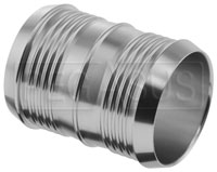
Pegasus sells these rather saucy splicing nipples. These are 1 1/2" parts to match the 1 1/2" hose I used. These couplers have a decent wall thickness so should not deform when I clamp down on them. I used the 5/8" sized couplers when I plumbed the heater in.
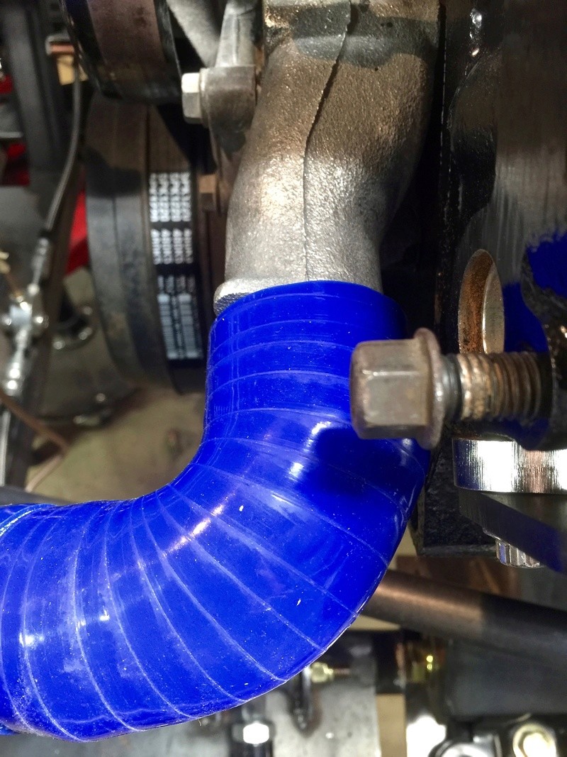
Here's the exit from the water pump. No clamps yet as the one I had on hand was too small...

... and the route down and toward the front of the car, avoiding the steering shaft and brake lines.

This routing avoids the steering rack, suspension and other moving components but stays close to the driver's side frame rails. I didn't really want to just cut across diagonally.

At the radiator, the hose makes a 90 degree turn and then a 45 degree dip downward to line up with the bottom port.
-Dave

Pegasus sells these rather saucy splicing nipples. These are 1 1/2" parts to match the 1 1/2" hose I used. These couplers have a decent wall thickness so should not deform when I clamp down on them. I used the 5/8" sized couplers when I plumbed the heater in.

Here's the exit from the water pump. No clamps yet as the one I had on hand was too small...

... and the route down and toward the front of the car, avoiding the steering shaft and brake lines.

This routing avoids the steering rack, suspension and other moving components but stays close to the driver's side frame rails. I didn't really want to just cut across diagonally.

At the radiator, the hose makes a 90 degree turn and then a 45 degree dip downward to line up with the bottom port.
-Dave
 Re: Classic R #27 Build - Cooling System

I had a go at making a -16 top hose with steel braided hose. I've never done one of these before. Everything they say about working with the braided stuff is true: my hands are ripped to shreds. The hose looks nice though. This one runs from the water neck to the inline filler.
I tried using various types of cutoff wheel to cut the hose, but they generate a lot of heat in the process of hacking through the stainless. I ended up making the cuts by hand with a fine toothed hacksaw. I wrapped the hose with blue masking tape before making the cut and had no difficulty getting the outer fitting over the cut end of the hose.
By the way, here's my tip for prepping the braided hose for assembly: use a stepped hole drill to clean up the inside edge of the cut end of the hose. When you start tightening down the fitting, it will make it easier for the inner part to align with the hose and the hose will be less inclined to push out.

Here's the hose and inline filler installed on the car. Ideally it's supposed to be the highest point of the system but I think the heater will be slightly higher. To bleed that part of the system I assume I can slacken off one of the AN fittings. The water neck's also slightly higher but it has its own removable plug for bleed and topup purposes. In the picture it looks as if the hose occludes one of the fuel injector ports but in practice it doesn't get in the way.

A second hose runs from the inline filler to the top port on the radiator hose. I routed it under the driver's side pushrod but it will need a bracket to keep it from flapping about.
Still to do: hose routing brackets, overflow bottle and hose, bracket for mounting the cooling fan, and all the other stuff I overlooked.
-Dave
 Re: Classic R #27 Build - Cooling System
It's taken an insanely long time to install the coolant fan. I've been busy with other stuff - finding a job for one thing - so there hasn't been as much time for the car this month as I had originally thought.
For the coolant fan I wanted to do something more robust than tie-wrapping the fan in place so I made a pair of custom mounting brackets from welded mild steel. This requires a lot of cutting of parts with odd angles from 3/4 x 1/8 mild steel bar, grinding to fit and then tack welding parts together. The brackets are asymmetrical reflecting the position of the mounting brackets on the radiator itself.

I've only tacked the brackets together at this stage. I assembled them with the radiator off the car flat on a worktable, then remounted the radiator and mounted the fan and bracket assembly as a whole in front of it.

Here's a closeup of how the bracket attaches to the fan. I used three mount points like this on each side. I ground the heads down on the bolts so they would fit into the pockets on the Maradyne fan, then made tabs and a framework to align to the mount points. The bolts can be loosened and the fan moved closer to the radiator core for a snug fit.
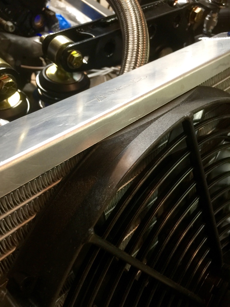
The top edge of the fan has a flat on it and I aligned that to the top of the radiator frame. There are no clearance issues under the hood. I chose not to center the fan on the radiator because there's limited room for the fan motor to fit behind where the radiator grille will be.
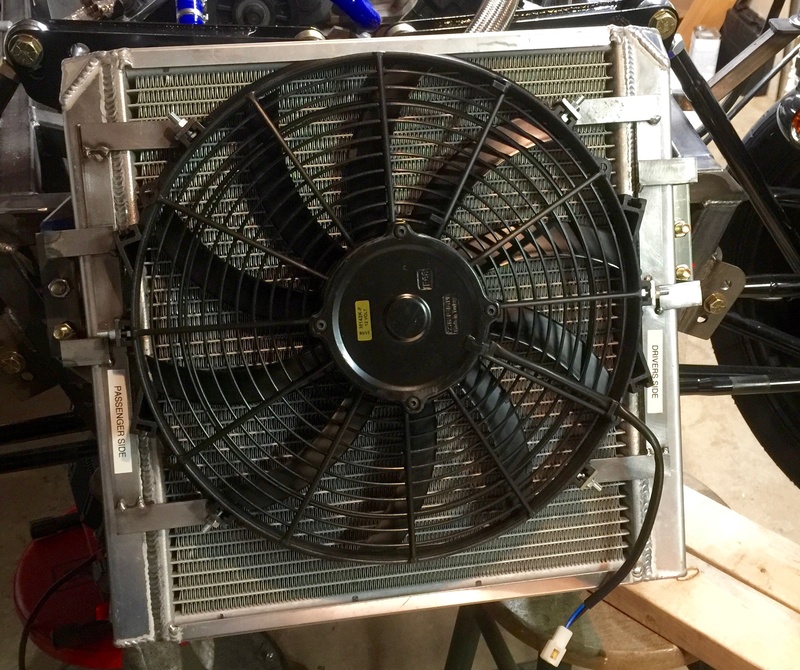
Here's the fan mounted on the radiator. The brackets use the same mount points and rubber isolation grommets as the radiator. I'm tempted to make up a temporary harness and run this directly off the battery to make sure the brackets hold up with the fan in motion. They seem robust enough though.
To complete these I'll need to finish the welds, file off the rough edges and then powder coat each bracket. Perhaps I'll add a cable clamp for the harness as well.
-Dave
For the coolant fan I wanted to do something more robust than tie-wrapping the fan in place so I made a pair of custom mounting brackets from welded mild steel. This requires a lot of cutting of parts with odd angles from 3/4 x 1/8 mild steel bar, grinding to fit and then tack welding parts together. The brackets are asymmetrical reflecting the position of the mounting brackets on the radiator itself.

I've only tacked the brackets together at this stage. I assembled them with the radiator off the car flat on a worktable, then remounted the radiator and mounted the fan and bracket assembly as a whole in front of it.

Here's a closeup of how the bracket attaches to the fan. I used three mount points like this on each side. I ground the heads down on the bolts so they would fit into the pockets on the Maradyne fan, then made tabs and a framework to align to the mount points. The bolts can be loosened and the fan moved closer to the radiator core for a snug fit.

The top edge of the fan has a flat on it and I aligned that to the top of the radiator frame. There are no clearance issues under the hood. I chose not to center the fan on the radiator because there's limited room for the fan motor to fit behind where the radiator grille will be.

Here's the fan mounted on the radiator. The brackets use the same mount points and rubber isolation grommets as the radiator. I'm tempted to make up a temporary harness and run this directly off the battery to make sure the brackets hold up with the fan in motion. They seem robust enough though.
To complete these I'll need to finish the welds, file off the rough edges and then powder coat each bracket. Perhaps I'll add a cable clamp for the harness as well.
-Dave
 Re: Classic R #27 Build - Cooling System
For the coolant expansion tank, I picked up an aluminum tank with hose/tube fittings, an internal overflow tube and aluminum brackets for about $70. The capacity is indicated as 550ml but I've not measured it to confirm.

There's a fairly deep space near the water neck, above the starter, that will accommodate a tank of up to about 3" diameter. The cylinder head has two threaded holes that are not being used for anything else so I decided to use them to mount the tank to. I cut a piece of steel stock and drilled it to match the hole locations. I'd kept the original bolts from these locations for reuse but I had to cut them down to about 3/4" to get them to thread into the head fully.

I tacked together a custom bracket from steel bar stock.

The expansion tank brackets are bolted directly to the new custom bracket.

The tank has to be inserted from the bottom and because this whole subassembly will be put together off the car, it's important to be sure that there is free access to the engine mounting holes when the tank is slid into place.
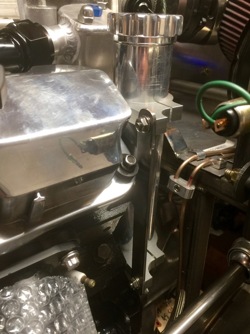
It fits nicely into that space near the water neck and there is sufficient clearance below to access the threaded -6 flare fittings. The overflow will be routed to a low point on the car (this is not a track car) and the line to the radiator cap will be constructed using 3/8 stainless hardline and fittings.

Viewed from above. The next job is to fabricate and attach the hardline, so I see more bending and flaring in my future.
-Dave

There's a fairly deep space near the water neck, above the starter, that will accommodate a tank of up to about 3" diameter. The cylinder head has two threaded holes that are not being used for anything else so I decided to use them to mount the tank to. I cut a piece of steel stock and drilled it to match the hole locations. I'd kept the original bolts from these locations for reuse but I had to cut them down to about 3/4" to get them to thread into the head fully.

I tacked together a custom bracket from steel bar stock.

The expansion tank brackets are bolted directly to the new custom bracket.

The tank has to be inserted from the bottom and because this whole subassembly will be put together off the car, it's important to be sure that there is free access to the engine mounting holes when the tank is slid into place.

It fits nicely into that space near the water neck and there is sufficient clearance below to access the threaded -6 flare fittings. The overflow will be routed to a low point on the car (this is not a track car) and the line to the radiator cap will be constructed using 3/8 stainless hardline and fittings.

Viewed from above. The next job is to fabricate and attach the hardline, so I see more bending and flaring in my future.
-Dave
 Similar topics
» Classic R #27 Build - Fuel System
» Classic R #27 Build - Exhaust System
» Classic R #27 Build - Lighting
» Classic R #27 Build - Frame
» Classic R #27 Build - Windshield
» Classic R #27 Build - Exhaust System
» Classic R #27 Build - Lighting
» Classic R #27 Build - Frame
» Classic R #27 Build - Windshield
Page 1 of 1
Permissions in this forum:
You cannot reply to topics in this forum