Classic R #27 Build - Hubs, Calipers, Flexible Brake Hoses
Page 1 of 1
 Re: Classic R #27 Build - Hubs, Calipers, Flexible Brake Hoses
Had a busy week and weekend working on the car. During the week I spent some time looking at the dash and deciding how to proceed.

This is the profile I came up with, made from 3/4" MDF. it's basically the same as the standard Stalker dash, but I wanted more of the Lotus Seven flavour - in a typical Seven, the lower line of the dash is flat right across. By way of compromise I kept some of the mid section, but cut away most of it to allow for the gear shift and for some usable cabin space under the dash.

The middle section around the tunnel. The radius is 3/8", made on the router table.
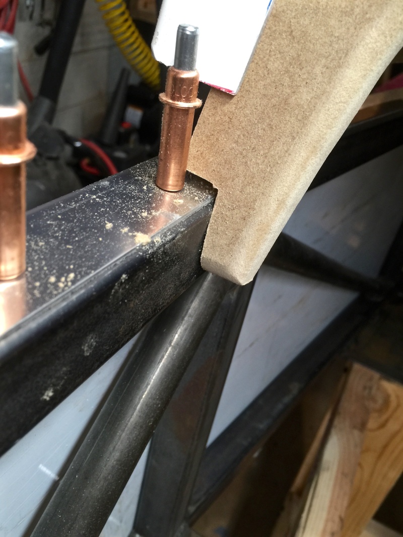
I kept the same profile at the ends but rounded over the very bottom edge. The next step will be to use this MDF former to shape up a piece of aluminum to match.
Over the weekend I powdercoated and refitted the front and rear spindles.

The spindles are an easy fit in the powdercoating oven I'm using but because they're a big lump of billet aluminum they take a bit longer to get up to 450F to flow out. They also take forever to cool down before fitting, but it's a nice feeling bolting a part onto your car that's still warm from the powdercoating oven.
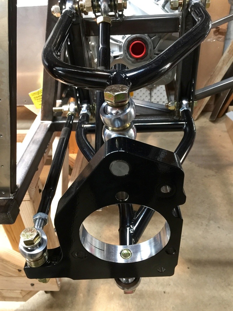
Here's the end result, re-installed on the chassis. Now I can press fit the front hub. My rear hubs are expected to arrive Monday and I may try to fit them Monday night.

Preassembled front hub on the bench. It's worth doing this step to ensure that the threaded holes are clear all the way through as the thread finish felt a bit rough in places. Note that the hole layout is asymmetrical: the holes with the shorter horizontal distance between them orient toward the top of the spindle.

Installation under way. I followed the build video here, tightening each bolt a little at a time to pull the hub into position. I used a little anti-seize compound around the hole.

Fully installed front hub. You can see the hole where the vehicle speed sensor would go. On these hubs there wasn't one installed. My spare set of rears has them but I haven't tried interchanging them yet. I assume they're hall effect sensors as there seems to be some sort of ferrite ring visible through the hole.
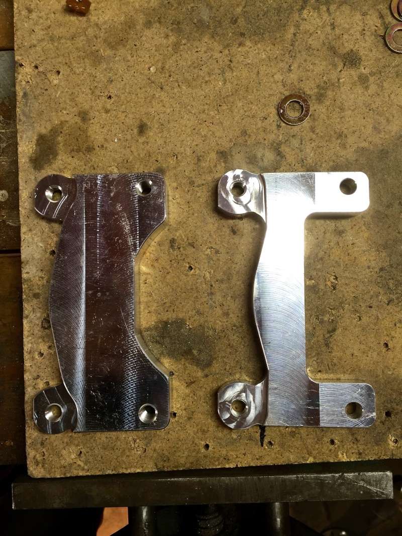
With the front hub in place I moved on to the brake caliper. It's held on with an aluminum adapter bracket and 1 1/2" bolts. You can see the front and rear brackets are slightly different: the front one, on the left, is slightly bigger than the rear and has all four holes tapped.

Front bracket kitted with its bolts and washers...

... and bolted onto the spindle.
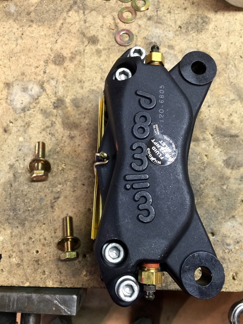
The caliper bolts onto the other two threaded holes in the caliper bracket, using the shorter bolts and a washer on each.

Prior to bolting the caliper on, the rotor has to be slipped on, then the caliper aligned over it and bolted down.

The completed rotor and caliper assembly minus the brake pads. EDIT: Note that I stuck the rear calipers on the front by mistake. The larger 6 piston ones belong at the front and these smaller ones go at the rear. These are 12.75" rotors from EBC, part number RK7171. The black finish on the face of the rotors will wear off in use. They weigh a ton and add enough weight to the front of the car that it wants to tip off the build table so I added jammed a stool under the front chassis to keep things under control.
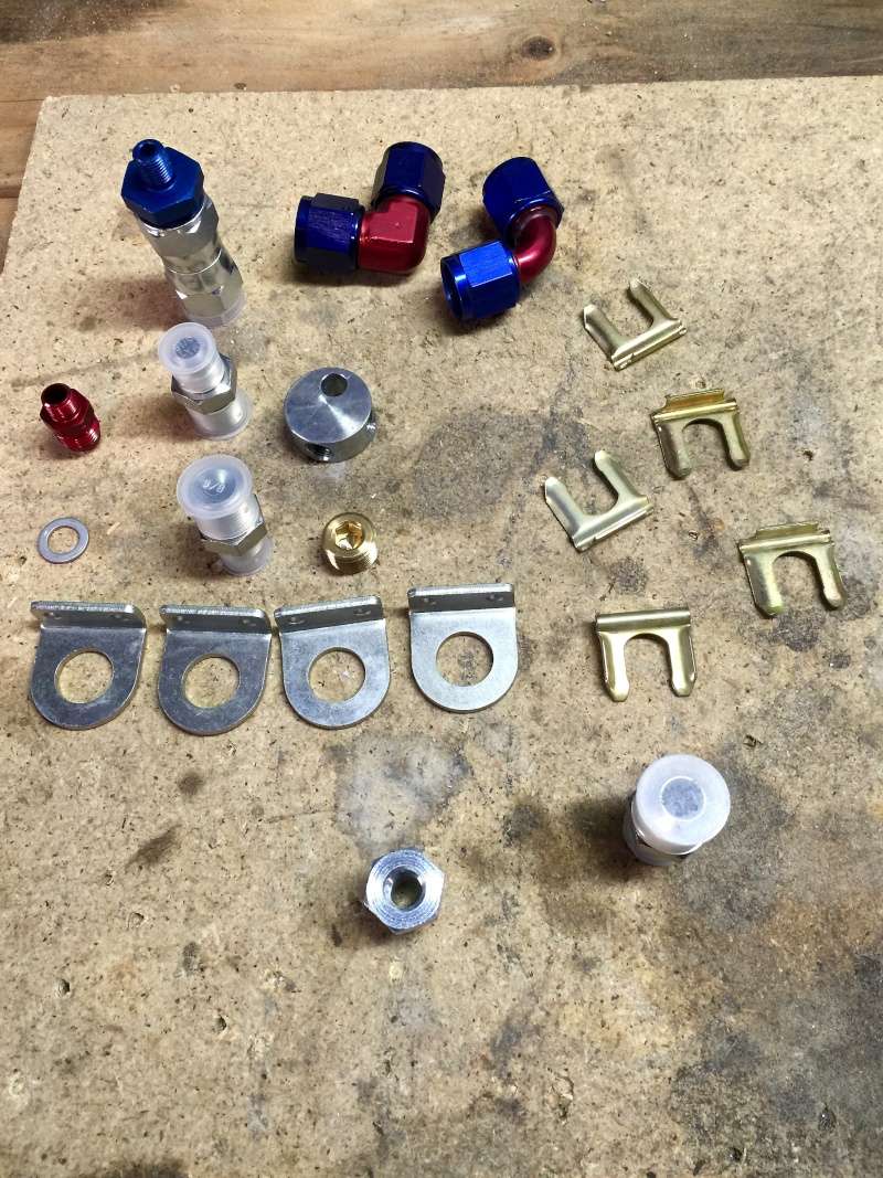
The brake line accessory bag has all sorts of bits and pieces in it. The round part is a brake line union - there are two, one for the front and one for the rear - that fit onto brackets that are already welded onto the frame. I mounted my front and rear brake unions with 1/4-28 1" machine screws, lock washers and nuts that I happened to have on hand. Maybe there's a bolt in the kit but it wasn't in the brake parts bag.

This is the doohickey that mates the brake hose to the caliper. One end is a 1/8-27 NPT male (according to the label on the caliper) and it screws into the back of the caliper. The hole is underneath the label. The other end is a JIC flare that will fit the brake hose connector. The build video indicates using thread sealant on the final build.
In terms of routing and mounting the lines, my kit deviated from the build video here in a couple of ways. First, the video shows the brake hose routing brackets as being welded onto the chassis. In my kit, they were supplied loose, and that's actually a good thing because my lower A-arms have a cross piece that the car in the video didn't have. That would have interfered with the brake hose had I installed the brackets in the place shown in the video resulting in the A-arm clouting the line constantly.

To avoid any contact points between the suspension/steering and the brake lines, I routed mine up the vertical chassis tube. I measured 3" up on the outer edge of the chassis tube, from the weld, and drilled two holes. This location should clear the steering shaft and any cooling components; it's a good distance from where the headers will be too.

Here's the routing I ended up with. I hope I didn't overlook anything that may get in the way.

Viewed from the outside. The flexible line has no contact points with anything with the steering rack being operated from left to right full lock. To finish this up I'll powder coat the brake hose brackets and caliper brackets.

At the back of the car, the bracket for the brake union is offset slightly to the left. The brake hoses seem to account for this as there is a shorter and a longer hose.

I roughed in the installation of the hoses but didn't complete it because my hubs/calipers aren't in place yet on the rear. Hope to get those installed Monday night.
-Dave

This is the profile I came up with, made from 3/4" MDF. it's basically the same as the standard Stalker dash, but I wanted more of the Lotus Seven flavour - in a typical Seven, the lower line of the dash is flat right across. By way of compromise I kept some of the mid section, but cut away most of it to allow for the gear shift and for some usable cabin space under the dash.

The middle section around the tunnel. The radius is 3/8", made on the router table.

I kept the same profile at the ends but rounded over the very bottom edge. The next step will be to use this MDF former to shape up a piece of aluminum to match.
Over the weekend I powdercoated and refitted the front and rear spindles.

The spindles are an easy fit in the powdercoating oven I'm using but because they're a big lump of billet aluminum they take a bit longer to get up to 450F to flow out. They also take forever to cool down before fitting, but it's a nice feeling bolting a part onto your car that's still warm from the powdercoating oven.

Here's the end result, re-installed on the chassis. Now I can press fit the front hub. My rear hubs are expected to arrive Monday and I may try to fit them Monday night.

Preassembled front hub on the bench. It's worth doing this step to ensure that the threaded holes are clear all the way through as the thread finish felt a bit rough in places. Note that the hole layout is asymmetrical: the holes with the shorter horizontal distance between them orient toward the top of the spindle.

Installation under way. I followed the build video here, tightening each bolt a little at a time to pull the hub into position. I used a little anti-seize compound around the hole.

Fully installed front hub. You can see the hole where the vehicle speed sensor would go. On these hubs there wasn't one installed. My spare set of rears has them but I haven't tried interchanging them yet. I assume they're hall effect sensors as there seems to be some sort of ferrite ring visible through the hole.

With the front hub in place I moved on to the brake caliper. It's held on with an aluminum adapter bracket and 1 1/2" bolts. You can see the front and rear brackets are slightly different: the front one, on the left, is slightly bigger than the rear and has all four holes tapped.

Front bracket kitted with its bolts and washers...

... and bolted onto the spindle.

The caliper bolts onto the other two threaded holes in the caliper bracket, using the shorter bolts and a washer on each.

Prior to bolting the caliper on, the rotor has to be slipped on, then the caliper aligned over it and bolted down.

The completed rotor and caliper assembly minus the brake pads. EDIT: Note that I stuck the rear calipers on the front by mistake. The larger 6 piston ones belong at the front and these smaller ones go at the rear. These are 12.75" rotors from EBC, part number RK7171. The black finish on the face of the rotors will wear off in use. They weigh a ton and add enough weight to the front of the car that it wants to tip off the build table so I added jammed a stool under the front chassis to keep things under control.

The brake line accessory bag has all sorts of bits and pieces in it. The round part is a brake line union - there are two, one for the front and one for the rear - that fit onto brackets that are already welded onto the frame. I mounted my front and rear brake unions with 1/4-28 1" machine screws, lock washers and nuts that I happened to have on hand. Maybe there's a bolt in the kit but it wasn't in the brake parts bag.

This is the doohickey that mates the brake hose to the caliper. One end is a 1/8-27 NPT male (according to the label on the caliper) and it screws into the back of the caliper. The hole is underneath the label. The other end is a JIC flare that will fit the brake hose connector. The build video indicates using thread sealant on the final build.
In terms of routing and mounting the lines, my kit deviated from the build video here in a couple of ways. First, the video shows the brake hose routing brackets as being welded onto the chassis. In my kit, they were supplied loose, and that's actually a good thing because my lower A-arms have a cross piece that the car in the video didn't have. That would have interfered with the brake hose had I installed the brackets in the place shown in the video resulting in the A-arm clouting the line constantly.

To avoid any contact points between the suspension/steering and the brake lines, I routed mine up the vertical chassis tube. I measured 3" up on the outer edge of the chassis tube, from the weld, and drilled two holes. This location should clear the steering shaft and any cooling components; it's a good distance from where the headers will be too.

Here's the routing I ended up with. I hope I didn't overlook anything that may get in the way.

Viewed from the outside. The flexible line has no contact points with anything with the steering rack being operated from left to right full lock. To finish this up I'll powder coat the brake hose brackets and caliper brackets.

At the back of the car, the bracket for the brake union is offset slightly to the left. The brake hoses seem to account for this as there is a shorter and a longer hose.

I roughed in the installation of the hoses but didn't complete it because my hubs/calipers aren't in place yet on the rear. Hope to get those installed Monday night.
-Dave
Last edited by comled on Mon Feb 15, 2016 6:31 pm; edited 1 time in total
 Classic R #27 Build - Hubs, Calipers, Flexible Brake Hoses
My rear hubs arrived today and while I was fitting them, I noticed that some oaf had put the rear calipers on the front spindles. It was probably that limey who did it. Anyway I had a word with him and he replaced them with the right ones.


Much better. The six-pot calipers belong on the front. The smaller ones belong at the back. I'll put them there tomorrow.


Much better. The six-pot calipers belong on the front. The smaller ones belong at the back. I'll put them there tomorrow.
 Classic R #27 Build - Calipers
A few more parts arrived yesterday and I was able to make progress on two areas.

First, the rear caliper and bracket assembly differ from the front in that the holes that mount the bracket to the spindle are not threaded, so the bolt has to pass through the bracket and into the threaded hole on the spindle, from the rotor side. The kit ships with bolts that are partially threaded. The unthreaded portion is longer than the thickness of the rear bracket (which is thinner than the front bracket) so they can't be fully tightened down. Also, they are too long too fit into the spindle if you already have the hub installed. I bought 1 1/4" bolts, fully threaded, from McMaster Carr to replace the ones that were in the kit. However, having assembled the bracket and caliper to the spindle I think these are too short so I'm going to order 4x1 1/2" 3/8-24 fully threaded bolts instead. Anyway, I assembled everything with 1 1/4" bolts for now.


I realize I'm going to have to temporarily fit the driveshafts and prop shaft in order to be confident in my brake hose routing. That's a job for another day though.


Another loose end cleared up: I resolved my front suspension pushrod assembly issue by replacing the 5/8" shank 1/2" hole heim joint with a comparable item but with a 5/8" diameter ball instead of the 3/4" ball. Evidently they come in different sizes and the wider one (top one in the picture) won't fit the channel in the A-arm.

First, the rear caliper and bracket assembly differ from the front in that the holes that mount the bracket to the spindle are not threaded, so the bolt has to pass through the bracket and into the threaded hole on the spindle, from the rotor side. The kit ships with bolts that are partially threaded. The unthreaded portion is longer than the thickness of the rear bracket (which is thinner than the front bracket) so they can't be fully tightened down. Also, they are too long too fit into the spindle if you already have the hub installed. I bought 1 1/4" bolts, fully threaded, from McMaster Carr to replace the ones that were in the kit. However, having assembled the bracket and caliper to the spindle I think these are too short so I'm going to order 4x1 1/2" 3/8-24 fully threaded bolts instead. Anyway, I assembled everything with 1 1/4" bolts for now.


I realize I'm going to have to temporarily fit the driveshafts and prop shaft in order to be confident in my brake hose routing. That's a job for another day though.


Another loose end cleared up: I resolved my front suspension pushrod assembly issue by replacing the 5/8" shank 1/2" hole heim joint with a comparable item but with a 5/8" diameter ball instead of the 3/4" ball. Evidently they come in different sizes and the wider one (top one in the picture) won't fit the channel in the A-arm.
 Similar topics
» Classic R #27 Build - Parking Brake
» Classic R #27 Build - Brake Line Installation
» Classic R #27 Build - Brake Booster, Dash, Pedals and Steering
» Classic R #27 Build
» Classic R #27 Build - Frame
» Classic R #27 Build - Brake Line Installation
» Classic R #27 Build - Brake Booster, Dash, Pedals and Steering
» Classic R #27 Build
» Classic R #27 Build - Frame
Page 1 of 1
Permissions in this forum:
You cannot reply to topics in this forum