Classic R #27 Build - Dash and Instrumentation
Page 1 of 1

Classic R #27 Build - Dash and Instrumentation
![]() by comled Sun Jun 12, 2016 10:38 pm
by comled Sun Jun 12, 2016 10:38 pm
Earlier this year I made the decision to swap out the regular dash for a custom vinyl-covered one (original post here). Over the weeks I have been working on shaping and smoothing the dash. This weekend I finalized the layout and got everything drilled out.

I started with a mock up - just some aluminum sheet cut to fit, and 1:1 replicas of the gauges plus the actual switches I intended to use. The mockup assumes a 13.75" steering wheel. I tried various combinations for the switches including an elaborate mechanism for mounting the switches on a sub panel behind the dash and actuating them remotely. I can't say that went terribly well. So all the switches and gauges are mounted directly on the face of the dash with two exceptions: the ignition switch, which will be mounted down on the tunnel cover near the gear shift, and the instrumentation dimmer switch which will go under the dash, out of sight but accessible from the driving position. That red swatch on the right hand side is the vinyl I plan to cover the dash with.

Here's a view of the dash with the gauge mounting holes drilled out and the gauges dry fit. I used a de walt 3 1/8" dia hole saw and 2 1/16" dia hole saw for the larger and smaller holes respectively. By the way, the steering wheel is a Momo Indy, 350mm dia if I remember right, temporarily mounted using a JEGS ball-bearing type quick release hub.

With all the switches and instruments in place it's starting to look more complete. Still a long way to go though. One little challenge I have to deal with is that the switchgear came from different manufacturers and therefore has slightly different styling on the panel nuts. I plan to make up a set of panel mounting nuts out of aluminum, all of which will have the same finish and styling and give a consistent look across the dashboard. The instrument and switch styling looks very 50's/60's British sportscar to me and that's the look I want to accomplish.
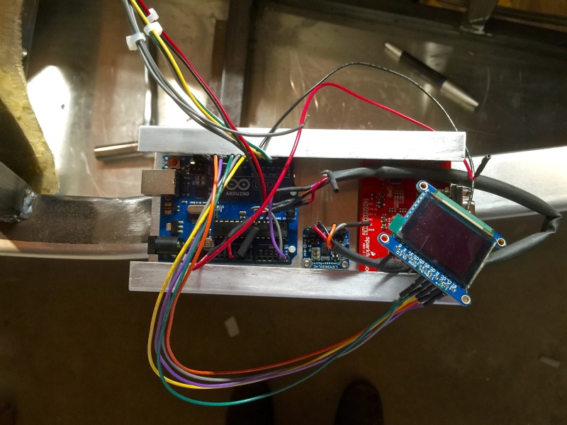
The far right-hand instrument with the white face is actually an empty housing that I had Speedhut supply. It's going to house an Arduino-based multifunction gauge based on a color OLED that acts as a compass/accelerometer and ODB2 parameter display - not very vintage I suppose but it will be amusing. This gauge will also house warning lamps for parking brake, MIL indicator and charge (high beam and turn signal lamps are built into the speedometer). This picture shows the prototype module I built back in Feb or March when there was still snow on the ground and I had a bit of time to spare. The accelerometer and compass features are working and I have coded the ODB2 readout but haven't tested it yet. On the dash there's a knob that you rotate to select different functions from the display. If it ever goes wrong and I can't source repair parts I'll just replace it with an ammeter or something more traditional.
-Dave
I started with a mock up - just some aluminum sheet cut to fit, and 1:1 replicas of the gauges plus the actual switches I intended to use. The mockup assumes a 13.75" steering wheel. I tried various combinations for the switches including an elaborate mechanism for mounting the switches on a sub panel behind the dash and actuating them remotely. I can't say that went terribly well. So all the switches and gauges are mounted directly on the face of the dash with two exceptions: the ignition switch, which will be mounted down on the tunnel cover near the gear shift, and the instrumentation dimmer switch which will go under the dash, out of sight but accessible from the driving position. That red swatch on the right hand side is the vinyl I plan to cover the dash with.
Here's a view of the dash with the gauge mounting holes drilled out and the gauges dry fit. I used a de walt 3 1/8" dia hole saw and 2 1/16" dia hole saw for the larger and smaller holes respectively. By the way, the steering wheel is a Momo Indy, 350mm dia if I remember right, temporarily mounted using a JEGS ball-bearing type quick release hub.
With all the switches and instruments in place it's starting to look more complete. Still a long way to go though. One little challenge I have to deal with is that the switchgear came from different manufacturers and therefore has slightly different styling on the panel nuts. I plan to make up a set of panel mounting nuts out of aluminum, all of which will have the same finish and styling and give a consistent look across the dashboard. The instrument and switch styling looks very 50's/60's British sportscar to me and that's the look I want to accomplish.
The far right-hand instrument with the white face is actually an empty housing that I had Speedhut supply. It's going to house an Arduino-based multifunction gauge based on a color OLED that acts as a compass/accelerometer and ODB2 parameter display - not very vintage I suppose but it will be amusing. This gauge will also house warning lamps for parking brake, MIL indicator and charge (high beam and turn signal lamps are built into the speedometer). This picture shows the prototype module I built back in Feb or March when there was still snow on the ground and I had a bit of time to spare. The accelerometer and compass features are working and I have coded the ODB2 readout but haven't tested it yet. On the dash there's a knob that you rotate to select different functions from the display. If it ever goes wrong and I can't source repair parts I'll just replace it with an ammeter or something more traditional.
-Dave

comled- Posts : 179
Join date : 2015-10-07
Location : New Hope, PA -

Re: Classic R #27 Build - Dash and Instrumentation
![]() by comled Sun Jun 19, 2016 11:26 pm
by comled Sun Jun 19, 2016 11:26 pm

More work on the dash today as I am preparing to do the vinyl covering next weekend. I hand filed the upper profile to match the dash hoop, and then built up the back of the dash with some fiberglass mat and resin to give it a little more rigidity. I'd noticed the thin aluminum was prone to flexing when operating switches. The extra rigidity will cut down on that flexing.

I cleaned it front and back and scuffed up the aluminum to give the vinyl adhesive something to key on. I tested the adhesive and vinyl on a scrap piece of aluminum to make sure they were compatible and in doing so it became clear that the glue wouldn't work as well on a smooth surface.
I'm basically ready to apply the adhesive and vinyl but that's a job for next week.
-Dave
comled- Posts : 179
Join date : 2015-10-07
Location : New Hope, PA -
Re: Classic R #27 Build - Dash and Instrumentation
![]() by comled Sat Jun 25, 2016 11:55 pm
by comled Sat Jun 25, 2016 11:55 pm
I spent today applying vinyl trim to the dash. The job turned out quite well. In order to get some sense of how to do this, I watched a few youtube videos and cast around the internet for advice. This video in particular was extremely helpful in understanding how to work around curved shapes. It seems the best adhesive to use is Weldwood Contact Adhesive for Landau tops but some folks complain that it damages their vinyl. I bought a gallon of it from yourautotrim.com. It's a spray grade adhesive but I brushed it on with a chip brush. I made a test part up to confirm that the vinyl and adhesive were compatible. Today was hot and so I took advantage of the good weather and worked outside - that ensured I had adequate ventilation and helped the adhesive set up quickly. Also, leaving the vinyl in the sun to warm up left it very pliable and easy to work with.

I started with a roughly two inch wide strip in the middle of the dash, along the top edge. The plan was to slowly work from the middle outwards. I glued up a couple of inches at a time, stretching the vinyl when I got to the compound curved surfaces. It took about 4 hours to complete the stretching and gluing.

Here's the finished result with the top edge trimmed to size.

This closeup shows one of the curved surfaces with the vinyl stretched over it. It went on relatively easily and I used a small roller and fingers and thumbs to work out any wrinkles that formed as I went along.

I was anxious to see what the gauges looked like against the vinyl trimmed dash. Here's the speedometer installed in the dash.

Speedometer and tachometer side by side with the scuttle added to finish the top edge.
It was a colossal amount of work to go this route but I really like the way it looks. Next I will trim the area around the steering shaft and cut out holes for the remaining instruments and switches.
-Dave
I started with a roughly two inch wide strip in the middle of the dash, along the top edge. The plan was to slowly work from the middle outwards. I glued up a couple of inches at a time, stretching the vinyl when I got to the compound curved surfaces. It took about 4 hours to complete the stretching and gluing.
Here's the finished result with the top edge trimmed to size.
This closeup shows one of the curved surfaces with the vinyl stretched over it. It went on relatively easily and I used a small roller and fingers and thumbs to work out any wrinkles that formed as I went along.
I was anxious to see what the gauges looked like against the vinyl trimmed dash. Here's the speedometer installed in the dash.
Speedometer and tachometer side by side with the scuttle added to finish the top edge.
It was a colossal amount of work to go this route but I really like the way it looks. Next I will trim the area around the steering shaft and cut out holes for the remaining instruments and switches.
-Dave
comled- Posts : 179
Join date : 2015-10-07
Location : New Hope, PA -
Re: Classic R #27 Build - Dash and Instrumentation
![]() by comled Sun Jul 31, 2016 10:22 pm
by comled Sun Jul 31, 2016 10:22 pm

Minor update on the dash - here is the current state of affairs with the steering shaft area trimmed (which of course you can't see in this picture because the steering wheel's in the way), all instrument holes cut out and instruments installed. The only remaining hole work is to cut the vinyl away from the last few switch holes and to install the switches for the heater fan, wash/wipe, hazard warning lights and multifunction gauge control.
-Dave
comled- Posts : 179
Join date : 2015-10-07
Location : New Hope, PA -
Re: Classic R #27 Build - Dash and Instrumentation
![]() by comled Mon Jun 19, 2017 6:58 pm
by comled Mon Jun 19, 2017 6:58 pm
In order to secure the dash, I added a metal tab to the frame. The headlamp dip/full switch will pass through both the tab and the front of the dash providing a secure mounting.
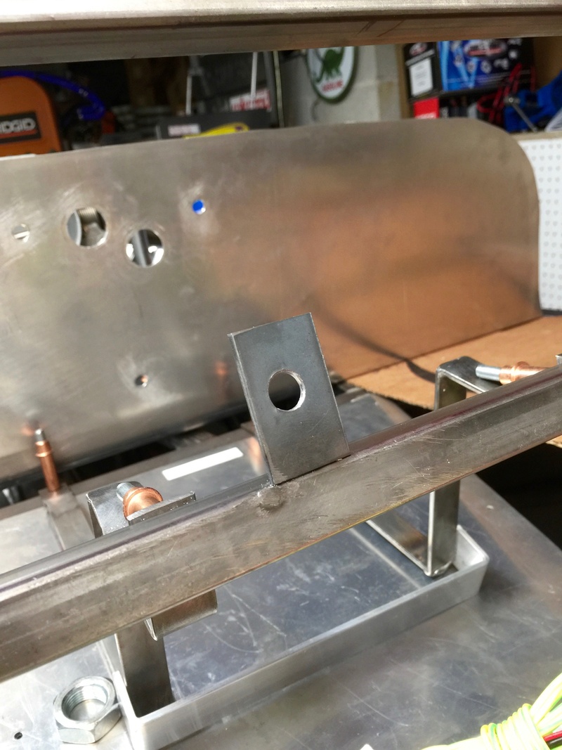
I cut and welded a piece of 1/8" thick mild steel to align with the hole in the dash already drilled for the switch. I reinstalled the dash, marked the center of the hole and drilled it in place.
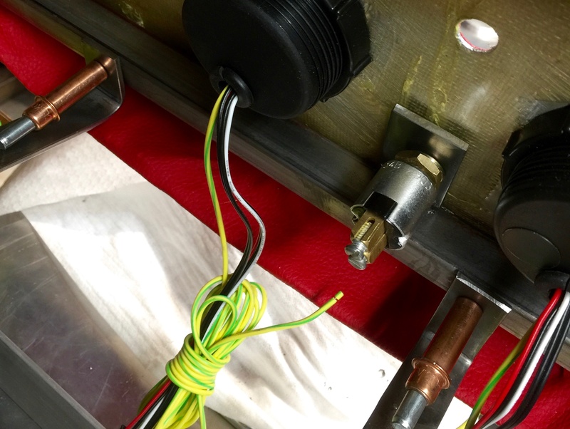
The threaded part of the switch passes through both the bracket and the front of the dash.

Switch viewed from dash side.
-Dave
I cut and welded a piece of 1/8" thick mild steel to align with the hole in the dash already drilled for the switch. I reinstalled the dash, marked the center of the hole and drilled it in place.
The threaded part of the switch passes through both the bracket and the front of the dash.
Switch viewed from dash side.
-Dave
comled- Posts : 179
Join date : 2015-10-07
Location : New Hope, PA -
» Classic R #27 Build - Brake Booster, Dash, Pedals and Steering
» Classic R #27 Build
» Classic R #27 Build - Hubs, Calipers, Flexible Brake Hoses
» Classic R #27 Build - Frame
» Classic R #27 Build - Lighting
» Classic R #27 Build
» Classic R #27 Build - Hubs, Calipers, Flexible Brake Hoses
» Classic R #27 Build - Frame
» Classic R #27 Build - Lighting
Page 1 of 1
Permissions in this forum:
You cannot reply to topics in this forum|
|
|